
Summary of Zener level-shifter drives high-side switch
This article discusses the challenges of controlling high-voltage loads with low-voltage microcontrollers (sub-5V) due to CMOS power dissipation trends. It proposes a simplified high-side switching circuit that replaces a standard NPN/PNP transistor pair with a Zener diode level-shifter, reducing component count while effectively driving 5V loads from 3.3V signals.
Parts used in the High-Side Switching Circuit:
- Microcontroller
- NPN transistor (T2)
- PNP transistor (T1)
- Zener diode (D1)
- Load resistor (R3)
- High-side switch
Microcontrollers, the heart of all modern electronic gadgets, are increasingly powered with sub-5V power supplies. This complicates the control of external loads powered by higher voltages.
The trend towards low voltage supplies is dictated by the fact that modern digital and mixed-signal integrated circuits are CMOS based, and with an ever increasing demand for higher frequencies, the only way you can control the power dissipation is by lowering the supply voltage. As a result, supplies have dropped from 5V to 3.3V and down to 1.8V for many popular, low-power microcontrollers in even the 8-bit range. Typically, 8-bit microcontrollers have a single power supply rail. 32-bit devices may have multiple power supply rails: 3.3V for the physical interface, and 2.5V or lower for internal operation. Some 32-bit devices also have triple power supply rails: 3.3V, 1.8V, and 1.1V for instance.
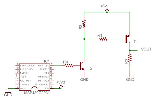
The reduced I/O supply voltage leads to increased complexity in handling high-side voltage switching. Figure 1 illustrates the conventional solution for controlling a 5V high-side switch, driven here by a 3.3V signal.
Figure 1 Standard method for a high side switching circuit
The low voltage microcontroller switches the NPN transistor T2, which in turn drives the PNP transistor T1. R3 represents the load. The load is grounded, but can also be a floating load with a suitable low-side switch.
This Design Idea proposes an alternative (Figure 2). In place of T2, we make use of Zener diode D1 of appropriate breakdown voltage.
Figure 2 A simpler high side switching circuit using a Zener diode
Traversing the path x→y→z for the transistor in ‘OFF’ and ‘ON’ conditions, the following equations can be used to calculate the value of the breakdown voltage for the Zener diode. A high microcontroller output voltage, added to the Zener breakdown voltage, is enough to turn off T1 as presented in equation (1). When the microcontroller output is set to low, the voltage at node y is low enough to turn the transistor T1 on as presented in equation (2).
For more detail: Zener level-shifter drives high-side switch
-
Why are modern microcontroller supply voltages dropping?
Lowering supply voltage is necessary to control power dissipation as digital and mixed-signal integrated circuits operate at ever-increasing frequencies. -
What complicates controlling external loads in modern electronics?
The trend toward sub-5V power supplies complicates the control of external loads that require higher operating voltages. -
How does the proposed design simplify the switching circuit?
The design replaces the NPN transistor T2 found in conventional solutions with a Zener diode D1 of appropriate breakdown voltage. -
How is the PNP transistor T1 turned off in the new circuit?
A high microcontroller output voltage added to the Zener breakdown voltage is sufficient to turn off transistor T1. -
How is the PNP transistor T1 turned on in the new circuit?
When the microcontroller output is set to low, the voltage at node y becomes low enough to turn transistor T1 on. -
Can the load be floating in this configuration?
Yes, the load can be a floating load provided there is a suitable low-side switch.
