Hi makers, do you want to own a wordclock?
There are a lot of nice instructions all over the web, but
- You’ve no access to a 3D printer and cnc machines to cut, laser or mill
- You don’t want to waste time and nerves fiddling with itsy-bitsy parts
- You don’t want to waste money, if there is an inexpensive solution doing the same
This Instructable is written for makers regardless of which experience level as long as you are familiar with
- A soldering iron
- Arduino IDE with Nodemcu / ESP8266 extension
- Basic wood working
What’s new in this Instructable
- How to make a multilayer wood / paper circuit
- How to build a 25x25cm wordclock for less than 40€
- How to make it within 3-4 hours from scratch
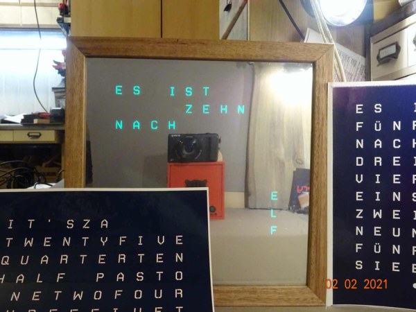
- The choice of English or German front panel
- Clock shows IP address at startup
What’s not new but cool, anyway
- Wifi connection accesspoint / station
- Getting time from a NTP server
- HTML interface to set display color and time offset for summer/winter
Here we go
Making a wordclock is cool! I’ve made some in the past using special machines like 3D printer, cnc mill and Silhouette cutting plotter. Each of them took a lot of time to build. Mostly weeding the text mask after cutting was a nightmare!
Reducing to the essential was the order of the day – especially due to Xmas and birthdays came up and I wanted to build 5 more clocks.
Is there a simple solution possible?
I’ve not reinvented the wheel, but this Instructable shows a cool approach to build electronic gadgets.
The answer is YES!
Design goals
- Easy and quick to make and use
- Using standard tools and parts
- Assembly without fiddling
- No need for a PCB
- Should be awesome
Summary for the impatient experienced maker
Hi, brothers in mind! Here comes your fast lane – fasten your seat belts, please.
- print the 4 sheets (one of the text masks, separator, electronics and stripes)
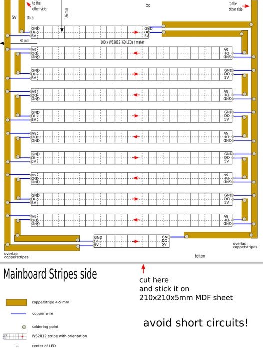
- take one MDF board and stick stripes sheet top left orientated on it
- flip the board and stick electronics sheet top right orientated on it
this is called “mainboard” from now on - take second MDF board and stick separator template top left oriented on it
drill 12mm holes now or later - stick copper tape snippets on mainboard stripes
5V, Gnd and data wrap around to electronics - flip mainboard and stick copper tape snippets in this order:
bottom layer (brown), isolation pads (red) and toplayer (green) - cut from LED stripe 1×6, 9×10 and 1×4 LED snippets in an order, to not hit the solder joints
- stick the LEDs on mainboard stripes side
follow the orientation arrows on template and LED stripe - connect with unisolated thin wire LEDs to copper tape
- flip mainboard and stick modules with double sided tape on electronics
fix USB breakout with tiny screws - connect with unisolated thin copper wire modules to copper tape
- solder copper tape overlappings on both sides of mainboard, if not already done
- drill separator (12mm), if not already done
- compile software and upload it. Libraries used:
NTPClient by Fabrice Weinberg, NeoPixelBus by Makuna and Time by Michael Margonis - see manual for setup and configuration.
- mount the whole Enchilada into an IKEA Ribba (23×23 cm / 9×9 inch)
1. acrylic screen with mirror foil sticked on it
2. separator with text mask (en/de) sticked on
3. mainboard
Fix it with some (hot-) glue - find a nice place for it and enjoy!
End of fast lane
How to do it in normal speed
First of all, oder the required parts as shown in the Supplies section if they are not in your grab bag.
To make a wordclock we need some electronics, some housing and last but important: the text mask.
What the heck is new in this Instructable?
As a maker I like to move off the beaten tracks and so I designed a multilayer paper/wood circuit to make things easier. The outcome was: making a wordclock is no longer rocket science.
We will start with the electronics to have fun in the beginning. The light separator will be made from a MDF panel with 100 holes. Boring can be boring – but it’s a way for everybody without special tools and machines to make this extraordinary clock. The project finishes with uploading the software and put it in an IKEA Ribba picture frame as housing.
Info
IKEA don’t sell Ribba anymore in black or white, the successor comes along as a really good looking medium brown acacia frame. I like it!
Some words about programming
The D1 mini is an ESP8266 board, so you need this extension in your Arduino IDE (see Step 8). Furthermore we need a library to grab the time from a NTP server, one to manage Time and of course one to talk to the NeoPixels. If you do not have installed them already, here is the list:
- NTPClient by Fabrice Weinberg
- NeoPixelBus by Makuna
- Time by Michael Margonis
Are you ready to start?
Good luck and have fun!
Supplies
The links below are pointing to german shops. Anyway, you will see which parts I mean 🙂
Electronics
- 1 Wemos D1 mini like this
- 100 WS28B12 LEDs as a stripe 60 LEDs / m (IP30 or IP65) like this
- 1 Level shifter like this
- 1 micro USB breakout board like this
Wiring
- 1m copper wire unisolated 0.25 mm (AWG 30, 0.01 inch) like this
- 2m copper tape adhesive 4-6mm mm (3/16 -1/4 inch) like thisorthis
conductive adhesive not required
Other parts
- 1 IKEA Ribba picture frame link
- 2 MDF sheets 210x210x5 mm (8.25 x 8.25 x 0.2 inch) (see text for details)
- 250x250mm self adhesive mirror foil (adhesive, not adherent!) like this
- Self adhesive glossy photo paper (inkjet or laser, matching your printer) like this
Chickenfeed
- 20cm double sided foam tape like this
- Tiny screws 2x5mm
- Small snippets of thin wood or cardboard to fix in picture frame
You’ll find all parts at Amazon, IKEA and the MDF boards cut to size at your Home Depot
If your stock is empty it will be in total 120€ for 3 wordclocks. This is 40€ for each!
Tools required
as mentioned – nothing special
- A soldering iron
- Scissors
- Boring machine (portable or drill press)
- wood drill 12mm (10 – 14mm)
- A coffee maker (not essential, but helpful)
Step 1: Print the Templates
What we do in this step
Let’s start with printing the templates on self ahesive glossy photo paper with suitable printer settings.
Printer setting is A4
Don’t use transparent foils for the text mask since the white medium act as light diffuser.
Stripes and Electronics act as assembly print for both sides of the first MDF board, Separator will be the boring template for the second MDF board. Mask English and Mask German are self-explanatory.
Tasks in this step
- Print the mainboard assembly prints (electronics and stripes)
- Print at least one of the text masks English or German
- Print the boring template
Hints
- The creative media sheets are selected because they are really sticky on wood. Of course it’s also possible to use plain paper for Electronics and Stripes and boring, as long as they are fixed all over to the board.
- The boring template will be removed afte drilling, so my experience says: use self adhesive photo paper.
- The text mask have to be sticked immovable fixed on the separator board and it is mandatory to have a photo quality to get an opaque saturation.
- Maybe you will try standard photo paper for this, but to fix it on the separator board without glue marks will be a callenge. Anywhere, do what you want – I use self adhesive photopaper for all of the sheets 🙂
Step 2: Prepare the LED Stripes
What we do in this step
In this step the long NeoPixel stripe will be cutted into proper snippets.
Trivia about NeoPixel stripes
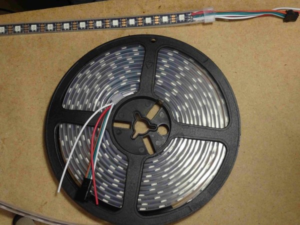
Neopixel WS2812 stripes are available in different configurations. We use a 5 meter stripe with 60 LEDs per meter. This will be enough for 3 wordclocks. Most of the suppliers offer their stripes in 3 different types:
- IP30 – naked stripe with 3M adhesive
- IP65 – stripe with no adhesive covered in a silicon shell
- IP67 – stripe sealed in silicon – don’t order this
IP30 is easy to use, if you bought IP65 you’ll need double sided tape to stick them but it’s also ok.
Info
LED stripes are made out of several sections each 30 LEDs long, soldered to one long stripe. Follow the cutting plan below, to avoid the necessity to separate the stripe at soldering joints.
Tasks in this step
- Remove the wires at the beginning of the stripe – in case of a new stripe
- Cut one segment 6 LEDs long as the top row – in case of a new stripe
- Cut nine segments, each 10 LEDs long
- Cut one segment 4 LEDs long (minute points)
Hints to desolder the wires from the stripe
- The manufacturer uses unleaded solder, you maybe need higher temperature or longer time to make it fluid.
- Don’t grill the LED!
Step 3: The 3-layer Wood/paper Circuit
What we do in this step
make our 3 layer paper/wood circuit board by sticking the copper tape and isolation pads on the 2 sides of the first MDF board. This board is called “mainboard” from now on.
What we need in this step
- One MDF sheet
- Mainboard assembly prints (electronics and stripes)
- Self adhesive copper tape
- The 4 isolation pads (or some scotch tape)
Tasks in this step
- Stick the stripes printout top left oriented on one MDF board
- Stick the electronics printout top right oriented on the other side
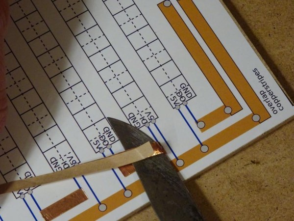
- Stick the copper tape on mainboard’s LED stripe side
5V, Gnd and Data wraps around to the electronics side - Stick the copper tape on mainboard’s electronic side
– start with bottom layer on brown assembly print
– next are the red isolation pads
– last is top layer on green assembly print
Hints
- The copper tape can be 3 to 6.5 mm in width (I use 4.5 mm)
- Conductive adhesive is not necessary
- If one of the isolation pads is lost, simply cut another one out of the spare photo paper or use any tape you’ll find.
Step 4: Sticking the LEDs

What we do in this step
Now we are going to stick our NeoPixel snippets on.
What we need in this step
- the mainboard with copper tape sticked on
- our prepared NeoPixel snippets
Tasks in this step
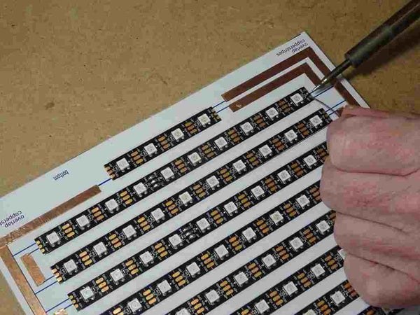
- Take the mainboard with LED side up and “top” mark on top 🙂
- Stick the 6 LEDs snippet on the top row, little red arrows showing the stripe orientation
- Repeat this for all other stripes – take notice of alternating orientation as shown by the arrows.
Hint
- If you’ve ordered an IP65 LED stripe instead of IP30, simply use double sided scotch tape to stick them.
- It’s not mandatory to use 5mm copper tape, but it’s easier to handle than a smaller one eg. 3mm
Up to 6.5mm copper tape is also suitable.
Step 5: Connect the LED Stripes
What we do in this step
Gentlemen start your engines – heat up your soldering irons
We are going to solder the LED side first.
What we need in this step
The board with LEDs on it 🙂
Thin unisolated copper wire as described in Supplies section
Tasks in this step
- Tin the stripe contacts – left side: data and 5V, right side data and Gnd
- Tin the copper tape at all relevant points
- Solder copper tape joints to connect them
- Solder the connections using the thin wire
Hints
- It’s not necessary to tin the thin copper wire
- Don’t beleive in conductiove adhesives. Solder the copper tape connections, please.
- Don’t make short circuit faults.
- Don’t grill the LEDs or the tiny capacitors near the LED’s Do connection pads.
Step 6: The Electronics
What we do in this step
Stick modules on their place and connect them to copper tape.
What we need in this step
- Mainboard
- D1 mini
- Level shifter
- USB breakout board
- Double sided foam tape
- 2 tiny screws
Tasks in this step
- Tin the stripe contacts – left side: data and 5V, right side data and Gnd
- Tin the copper tape at all relevant points
- Solder copper tape joints to connect them
- Solder the connections using the thin wire
Hints
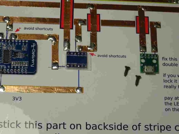
- Mount the modules correct oriented according to the printed pictures.
- Ensure that you’ve received the correct level shifter, the others are standard.
Step 7: Separator and Text Mask
What we do in this step
Now we are on the home stretch and the only boring job starts – the boring 🙂
What we need in this step
- The second MDF board
- The boring template called Separator
- A boring machine
- A 12mm wood drill
Tasks in this step
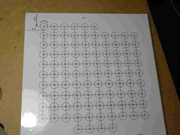
- Stick the Separator boring template top left oriented on the board.
- Center mark the holes (I recommend this).
- Drill the 100 holes from first side.
- Remove boring template sticker – or whatever is left of it
- Flip the board and drill. The tiny holes from wood drill’s tip will auto center the drill now.
There are many approaches to drill holes in wood. My experiences say it’s a good practice to drill from both sides. The wood drill’s tip should poke out a little bit (1mm) so it will leave a mark on the other side in the shape of a tiny hole. If you allow the drill to find this hole with it’s tip the drill will self center. This is exact enough for a light separator and really quick to make.
(see video part 2)
Hints
- Use a wood drill (see picture)
- It is much more easier to first center punch the bore position.
You can do this with a nail in case of you do not own a center punch. - Drilling nice holes in wood without ugly edges is difficult. There are 2 tricks:
1) Use a sacrificial plate to drill into, or
2) Adjust the deepth stop at your drilling machine to drill only so deep, that the little tip of your wood drill makes a tiny hole on the other side of the board. Then flip the board and drill from the bottom side. The little hole is your center mark. I prefer this!
Source: Wordclock – No Special Tools Required! Easy to Build