
Contents
hide
Summary of Woooshing leds – Rotated animation by arduino
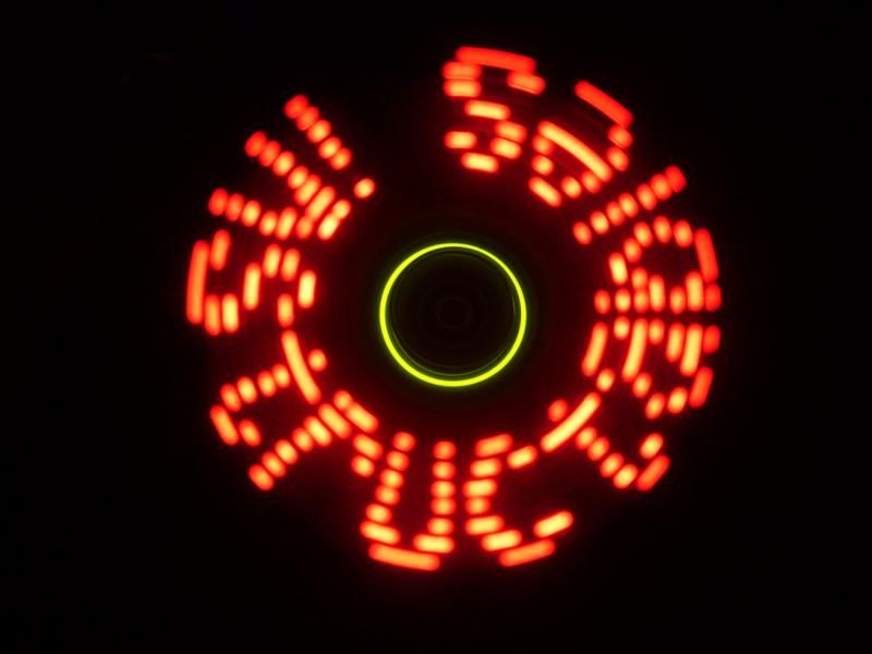
This project creates an air-glowing display by rotating a matrix of LEDs controlled by an Arduino. As the platform spins, rapid LED blinking generates the illusion of floating text or shapes in mid-air. The build involves assembling electronics on a circular matrix, mounting it on a DC motor with a wooden base, balancing battery packs for stability, and powering both the logic board and the motor separately.
Parts used in the Air Drawing Project:
- Arduino microcontroller
- 7 simple LEDs
- 420 Ohm resistors
- Circular matrix board
- Simple DC motor with removable shaft adapter
- Piece of wood for platform and base
- Small screws and long bolts
- Plastic sheet for electrical isolation
- Two identical battery packs
- Zip ties
- Nokia charger (modified to 9V connector)
- Door lock lid
- C-clamp
This project allows you draw in the air letters, symbols or other shapes – as you like.
Controlled by the Arduino, the 7 simple leds blinking on and off – creating the illusion of floating text in the air.
This combination of simple components with a unique program, allows to create this instructable.
Step 1: Assembling the electronics
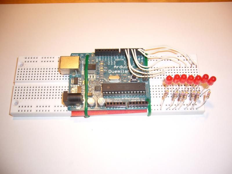
Place the leds near the edge of the matrix, so the circle it draws will be as wide as possible.
Note the polarity of the leds to be oriented in the same direction.
(You can use leds in different colors as I did with the WOOOSH case).
(You can use leds in different colors as I did with the WOOOSH case).
Place the Arduino near the center of the matrix and mount it to the matrix.
I used simple wires for that.
Since the bottom part of the Arduino has some conductors – I used a piece of plastic sheet as an isolator from the matrix.
Connect one side of the leds to the IO of the arduino (ports 1-7, leaving port 0 for the trigger).
Use suitable resistors and connect the other leg of the leds to the ground.
I used the bottom rail of the matrix as a common ground.
I used 420 Ohm resistors.
Step 2: Installing the platform on the motor
Now that you have the main electronic installed, you can install it on the motor – that will rotate all the platform (the matrix).
What you need is a simple DC motor (preferable with a removable shaft adapter), a piece of wood and two small screws.
I marked on the wood the required width I needed, the location of the holes for the bolts and for the shaft from the motor.
Then I drilled and sawed upon the marks.
I used the holes in the matrix to attach the wood to the matrix – using the bolts.
Note that the bolts must be long enough to grab the matrix – without passing to the other side and damage the Arduino.
I have inserted the shaft adapter into the drilled hole – using some force. The insertion planned to be “press fit” since the forces the shaft feels are not negligible.
Step 3: Installing the battery packs
Since the platform is turning, and the Arduino needs its food (power) – the simplest way was to install the batteries on the matrix itself – so they will rotate together.
For that, I used two identical battery packs and placed them on the opposite sides of the board – so they will balance each other.
I used simple zip ties to mount it to the matrix.
Try to install the batteries (additional weight) as closer as possible to the rotation center.
That way – the balancing problems you’ll have to deal with will be smaller.
After mounting the battery packs, connect the wires so the batteries will be in row, to reach 6 volts to operate the Arduino.
Think about a way to switch the board on and off.
I used the power plug to the arduino as my power switch – and later (when I got lazy of plugging it in and out) I have simply pulled up one of the power chord from the board.
Step 4: Fixing the motor to the world
For fixing the motor to a stationary object, you have to use a rigid base, so it will hold the small (or big) vibrations of the rotation – especially before the balancing was completed.
I used a nice piece of wood and a C-clamp – mounting the wood to a solid table.
Then, I used the lid of a door lock and zip ties to mount the motor to the wood.
Step 5: Powering the motor
The power source I used for the motor was an old Nokia charger.
I have changed its connector to be as a 9 Volts battery connector.
I used this connector because it allows you to snap on one of the terminals and then – by turning the two connectors – you can connect and disconnect the other terminal.
Step 6: Balancing the rotating platform
Once the system is installed and secured to the table, it can start turning.
In the beginning, allow the matrix to turn slowly, and see if everything is well muted and there is nothing loose.
When allowing to turn faster, be aware for any excessive vibrations (which will probably accrue in the beginning), caused by the weight being unbalanced around the turning center.
Try balancing the system by sliding the batteries to one way or another, until the vibrations decrease to minimal level.
You can also move the electric components for balancing – but it is more complicate and less efficient, since the mass of the batteries is significantly bigger (and simpler to move tham).
For more detail: Woooshing leds – Rotated animation by arduino
- How does the device create the illusion of floating text?
The Arduino controls seven simple LEDs that blink on and off while the platform rotates, creating the visual effect of letters or shapes drawn in the air. - What is the best way to position the LEDs on the matrix?
Place the LEDs near the edge of the matrix so the circle they draw will be as wide as possible. - Why should batteries be installed closer to the rotation center?
Installing batteries closer to the center reduces balancing problems and minimizes vibrations caused by unbalanced weight. - How do you ensure the Arduino is safe from short circuits on the matrix?
Use a piece of plastic sheet as an isolator between the conductive bottom part of the Arduino and the matrix. - What voltage is required to operate the Arduino in this setup?
The batteries are connected in series to reach 6 volts to operate the Arduino. - Can I use different colors for the LEDs?
Yes, you can use LEDs in different colors, though all must be oriented in the same direction regarding polarity. - How is the motor secured to the table?
Mount a rigid piece of wood to a solid table using a C-clamp, then attach the motor to the wood using a door lock lid and zip ties. - What power source was used for the motor?
An old Nokia charger modified with a 9 Volts battery connector was used to power the motor.
