Summary of Wiring of the Solenoid Valves
Overview of Wiring for the Salinity Sensor — Summary: The article describes a cascade-switched circuit where Arduino digital outputs drive NPN transistors that energize 5V relay coils, which in turn switch 12V power to solenoid valves (and a heater). Relay coils include flyback diodes; coil-side wiring ties relays to the Arduino 5V rail and ground via 220 Ω base resistors. Contact-side wiring sends 12V and ground to the solenoids; LEDs indicate relay activation on two relays.
Parts used in the Cascade Control Circuit:
- Arduino (microcontroller)
- Solenoid valve(s)
- 12V power supply
- 5V power supply (from Arduino)
- SPST relays (5V coil)
- NPN transistors (one per relay)
- 220 Ω base resistors
- Flyback (power) diodes across relay coils
- Breadboard
- Jumper wires (various colors: brown, yellow, blue, red, green, black)
- Indicator LEDs (for relay status)
Overview of Wiring for the Salinity Sensor
Other pages describing fish tank wiring:
Return to the main page for the fish tank wiring.
Schematic
The following schematic shows the circuit for supplying power to one of the solenoid valves.
The power to the solenoid comes from the 12V power supply circuit. The relay and the transistor are powerd from the 5V circuit, which is fed from the Arduino.
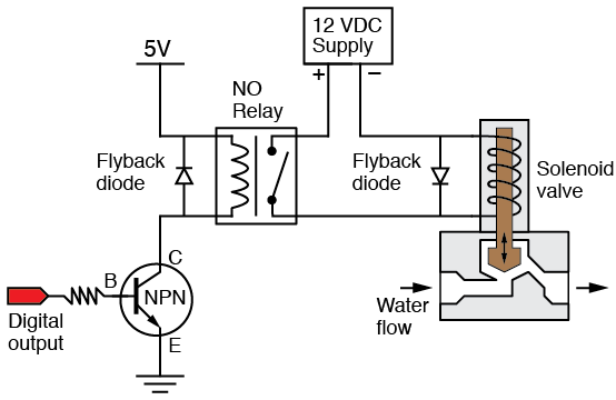
Cascade Switching
The solenoid is controlled by a cascade-switched circuit. A digital output pin of the Arduino is connected to the base of a transitor which controls the current to a normally open, SPST relay. When the relay coil is energized, it closes the contacts, which allows current from the 12V supply to flow through the solenoid. When the solenoid coil is energized, the valve opens, allowing water to flow from the reservoir into the fish tank.
The following photograph shows coil-side view of three relays. Two of the relays control separate solenoid. The third relay controls the heater. The wiring for the three relays is identical. The short red and green jumpers connect the relay circuit to the 5V power rail along the nearest edge of the breadboard.
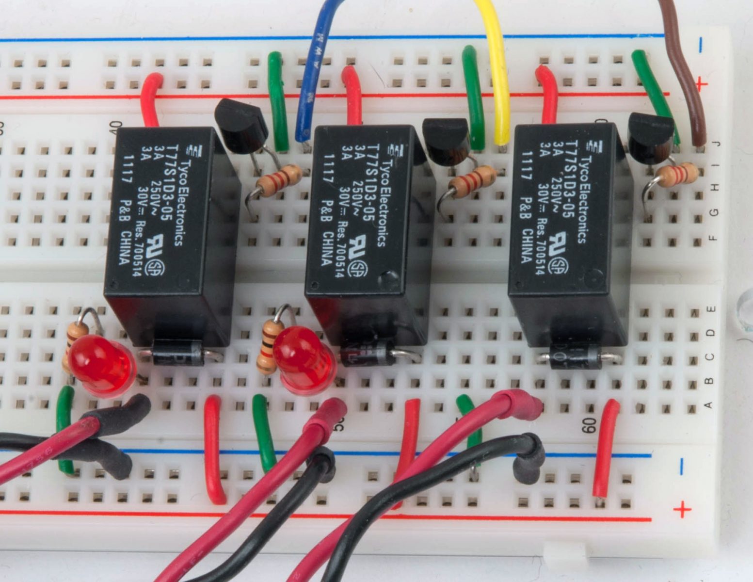
The brown, yellow and blue wires are connected to digital I/O pins on the Arduino. Each of those wires is connected to an NPN transistor by a 220 Ω resistor. The transistors are on the ground side of the relay coil. Power diodes are in parallel with the relay coil act as snubbers to the charge stored in the coil. When the current to the coil is switched off, the snubber diodes (a.k.a. flyback diodes) allow the electro-magnetic field in the coil to safely dissipate through the coil windings.
The following photograph shows the contact side of the relay circuit. There are three sets of long read and black leads that connect the relays either to one of the two solenoid valves or to the heater. Two of the three relays have red indicator LEDs to provide visual confirmation that the contact is closed. The rightmost relay circuit has its LED circuit removed to make the connection to the solenoid leads more clear.
For more detail: Wiring of the Solenoid Valves
- How is the solenoid controlled?
Arduino digital output drives an NPN transistor which energizes a 5V relay coil; the relay contacts switch 12V to the solenoid. - Where does the solenoid get its power?
The solenoid receives power from the 12V power supply circuit through the relay contacts. - What powers the relay and transistor?
The relay coil and transistor are powered from the 5V circuit fed from the Arduino. - Why are diodes used across the relay coils?
Power diodes act as flyback snubbers to safely dissipate the coil's stored charge when switched off. - How are the transistors connected in the circuit?
Each Arduino I/O pin connects through a 220 Ω resistor to the base of an NPN transistor, which is placed on the ground side of the relay coil. - How is visual confirmation of relay activation provided?
Two of the relays have red indicator LEDs to show when the contact is closed. - How are relay circuits tied to the breadboard power rail?
Short red and green jumpers connect the relay circuit to the 5V power rail along the breadboard edge. - Can the same wiring control multiple solenoids and a heater?
Yes; the photograph shows three identically wired relays controlling two solenoids and one heater.