Summary of Wireless Bell System
This project solves the issue of a faint class-change bell in a high school by creating an affordable, wireless repeater system. Using Arduino microcontrollers, a master station detects the main bell's sound via a sensor and broadcasts a signal to multiple slave stations equipped with bells. This setup replicates the alert across wide areas without expensive wiring or complex wireless infrastructure, offering a customizable solution for similar environments.
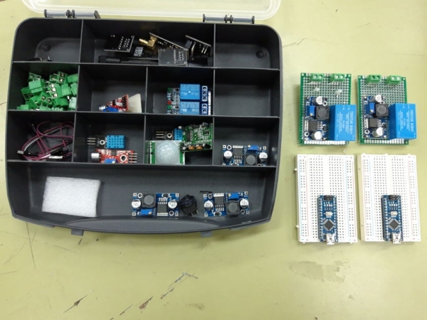
Parts used in the Wireless Bell System:
- NANO board
- NANO expansion board
- NRF24L01 adapter
- NRF24L01 + antenna
- Sound sensor detector
- Relay
- Bell
- 5V, 3W power supply
The problem that fix this project is the following: at the high school where I work, the class-change bell doesn´t sound loud enough everywhere and sometimes it causes some problems. Install a new wired class-change bells or buy a wireless bell system isn´t possible by the moment.
This project could be useful too, for everybody that need to replicate a main bell in a wide area without install a wired or wireless system bell, not expending much money and, of course, made by you.
Thinking in a solution and looking for similar projects, I found the followings projects here in instructables: Wireless Doorbell transmitter and Wireless Doorbel receiver. There was what I need but instead of using PIC microcontrollers I have decided to use Arduino microcontrollers and its components.
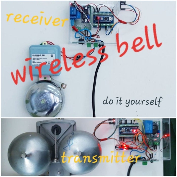
So, I proposed to the high school principal a simple and easy solution: to build a wireless class-change bell system. The solution is to install closed to the class-change bell a device with a sound detector controlled by a microcontroller that sends a signal to others receivers stations with bells when the class-change bell sounds. It´s easy and cheap.
See below the solution implemented it and how it works.
Step 1: List of Material
The solution implemented is based in a master/slave model where the master station or transmitter station is installed near the main class-changed bell and the slaves or receiver stations are installed in differents places. In this project we have configured the sound sensor station and only one bell repeater but it is possible to configure more ones. Initially the system is configured for five receivers stations but you can modify it.
So the material for the transmitter station is the following:
- NANO board
- NANO expansion board
- NRF24L01 adapter
- NRF24L01 + antenna
- Sound sensor detector
- 5V, 3W power supply
and the material for each receiver station:
Step 2: How to Connect and Program a Receiver Station
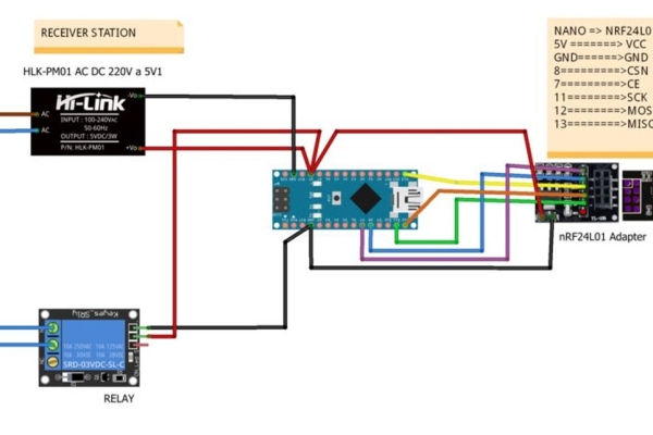
A receiver station is continously listening the wireless network waiting for the activation signal sent by the transmitter station manually or automatically when the main bell rings. While the signal is been receiving, it activates the relay to connect the secondary bell.
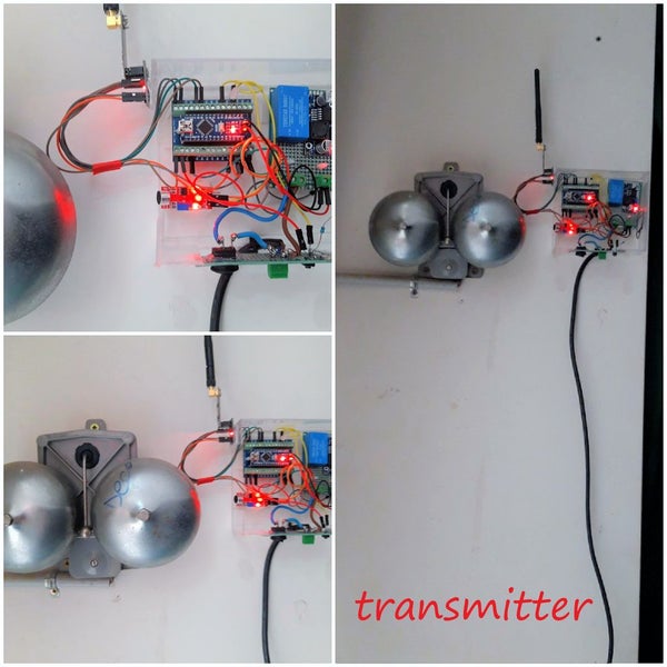
Step 3: How to Connect and Program a Transmitter Station
The transmitter station is continously measuring the sound level using the sound sensor installed close to the main bell to detect when it rings. While the main bell is ringing it is sending the activation signal to all the receivers station. Moreover I have installed a button to send the activation signal manually in case the main bell is out of service. While the button is pushed the station is sending it.
Step 4: Configuring the Transmitter Station
As you can see in the picture 2, the measurements before and after the main bell rings are stable (150, 149, 151, 149, ….), but when the main bell rings the analog measurements change between 95 and 281. The sketch I have programmed (see picture 2 and 3) will automatically detect the stable measuremet and will send a signal to the receivers stations when the diference, in absolute value, between the stable value and the current measurement is upper to a fixed threshold and remains during a number of readings.
For this project this value is fixed to 4 (4% up or lower the stable value) as you can see in the code below.
To configure this value, you have to do the following:
- You have to build the transmitter station with the sound sensor and install it near the mail bell (picture 1 or picture 4)
- Download and load the sketch “transmitter.ino” (see previous step)
- Test if the led remains on while the bell is ringing.
- If the led is off, you have to change the threshold (“min_threshold_to_send_signal” in the code below) to adjust the sound sensor to your bell and repeat the test. .
- If after several trials the led is on when the bell rings and off when it doesn’t rings, you have finished the configuration.
You can modify, if you need it, the delay time between two measurements (“delay_between_reads”) or the maximun level sound threshold to consider the same level sound (“max_threshold_to_consider_same_value”).
#define delay_between_reads 200
float min_threshold_to_send_signal = 4.0;
float max_threshold_to_consider_same_value = 1.0;
Step 5: Final Installation
Step 6: From the Beginning …
Source: Wireless Bell System
- What problem does this project solve?
The project addresses the issue of a class-change bell that is not loud enough everywhere in a high school. - How does the transmitter station detect the bell ringing?
The transmitter continuously measures sound levels using a sound sensor installed near the main bell. - Can the system be triggered manually?
Yes, a button is installed on the transmitter to send activation signals manually if the main bell is out of service. - How many receiver stations can be configured?
The system is initially configured for five receivers, but it is possible to configure more ones. - Does the system require wired connections between stations?
No, the system uses a wireless network with NRF24L01 modules to transmit signals from the master to the slaves. - What determines when the transmitter sends a signal?
A signal is sent when the difference between the stable measurement and the current measurement exceeds a fixed threshold. - Is it possible to adjust the sensitivity of the sound sensor?
Yes, you can modify the min_threshold_to_send_signal value in the code to adjust the sensitivity. - What happens when a receiver station gets the activation signal?
The receiver activates its relay to connect and ring the secondary bell.