Summary of What are Tantalum Capacitors?
This article details Tantalum capacitors, covering their composition, specifications (form factors like SMD/THT, standards, and capacitance formulas), construction methods for solid and wet types, and applications in electronics. It compares them with ceramic capacitors through testing on temperature stability and reliability, highlighting advantages like high capacitance density and stability, while noting risks like thermal runaway.
Parts used in the Tantalum Capacitor Project:
- Tantalum metal anode
- Oxide dielectric layer
- Conductive cathode
- Manganese dioxide coat
- Graphite layer
- Silver paint layer
- Semi-liquid electrolyte paste
- Carbon layer
- Lead wire leads
- Surface mount termination contacts
Catalog
Ⅰ What are Tantalum Capacitors?
Ⅱ Tantalum Capacitors Specifications
2.1 Form Factor
2.2 Standards
2.3 Capacitance
Ⅲ SMD Tantalum Capacitors
Ⅳ Applications for Tantalum Capacitors
Ⅵ Tantalum vs. Ceramic Capacitor Testing
6.1 Tantalum vs. Ceramic Capacitor IR Life Test
6.2 Tantalum vs. Ceramic Comparative Testing
Ⅶ Why Use Tantalum Capacitors in Your PCB Design?
Ⅰ What are Tantalum Capacitors?
Tantalum capacitors are an electrolytic capacitor subtype. They are composed of tantalum metal, which serves as an anode, a layer of oxide that serves as a dielectric, and a conductive cathode. Tantalum allows for the formation of a very thin dielectric layer. As a result, the capacitance value per volume is higher, the frequency characteristics are superior to many other types of capacitors, and the stability over time is excellent. Tantalum capacitors are generally polarized, which means they can only be connected to a DC supply if the terminal polarity is correct. The disadvantage of using tantalum capacitors is their unfavorable failure mode, which can result in thermal runaways, fires, and small explosions. However, this can be avoided by using external failsafe devices such as current limiters or thermal fuses. Tantalum capacitors can now be found in various circuits, including laptops, the automotive industry, cell phones, and others, most commonly as surface-mounted devices. Surface-mount tantalum capacitors take up much less space on the printed circuit board and allow higher packing densities.
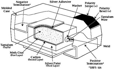
A cutaway view of a solid tantalum capacitor is shown in the image below. It’s worth noting how thin the coatings around the tantalum core are (manganese dioxide cathode, carbon, silver paint).
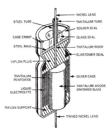
Wet tantalum (electrolytic) capacitors differ from solid tantalum capacitors in that a semi-liquid electrolyte paste serves as a second electrode; these devices are similar to aluminum electrolytic capacitors, which use solid aluminum anodes. Electrolytic capacitors in general have very high capacitance values but are unsuitable for AC power applications due to the required polarity, but they are widely used in DC power supplies. Tantalum capacitors have a longer shelf life, better temperature resistance, and higher capacitance values than aluminum electrolytic devices, but they are more easily damaged by constant voltages as low as 1.5 V. A cutaway view of a wet tantalum capacitor is depicted in the diagram below.
Ⅱ Tantalum Capacitors Specifications
2.1 Form Factor
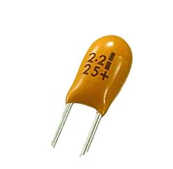
Tantalum capacitors are typically available in two configurations: leaded (or through-hole) and surface mount (SMT).
Leaded capacitors have long wire leads that are soldered to a PCB to form an electrical connection. Through-hole technology (THT) is used in these devices, allowing for strong mechanical connections. THT capacitors are required to be relatively large and have generally been replaced by surface mount products.
Surface mount (or chip) capacitors are attached to the top of a PCB with very short leads, flat contacts, or other types of termination. SMT devices are smaller and less expensive to produce than their older THT counterparts.
2.2 Standards
Tantalum capacitors may be manufactured to one or more various standards, including:
2.3 Capacitance
Two related formulas can be used to calculate the amount of charge on the plates or the maximum capacitance of the device.
Capacitance is calculated as:
where:
C = capacitance
Q = charge
V = voltage
If the applied voltage and capacitance values are known, we can also find the charge by rearranging this formula:
Capacitance can also be calculated in relation to a capacitor’s geometry:
where:
C = capacitance
Ε = permittivity of dielectric
A = plate area
d = distance between plates
This equation demonstrates that capacitance is independent of applied voltage and charge and is only a function of the geometry and dielectric material of the device.
Farads are extremely large units used to measure capacitance. The majority of capacitors are rated in micro- or picofarads.
Ⅲ SMD Tantalum Capacitors
Tantalum surface mount capacitors are widely used in modern electronic equipment. They provide reliable service and allow for high capacitance values to be obtained within the small package sizes required for modern equipment when designed with sufficient margins.
Aluminum electrolytic types were initially unavailable in surface mount packages due to their inability to withstand the temperatures required for soldering. As a result, tantalum capacitors that could withstand the reflow soldering process were almost the only option for high-value capacitors in surface-mount assemblies (SMT). Despite the availability of SMD capacitors, tantalum remains the capacitor of choice for SMD due to its excellent cost, size, and performance parameters.
| Surface Mount Tantalum Capacitor Size | ||
| Designation | Size (mm) | EIA Designation |
| Size A | L3.2 x W1.6 x H1.6 | EIA 3216-18 |
| Size B | L3.5 x W2.8 x H1.9 | EIA 3528-21 |
| Size C | L6.0 x W3.2 x H2.2 | EIA 6032-28 |
| Size D | L7.3 x W4.3 x H2.4 | EIA 7343-31 |
| Size E | L7.3 x W4.3 x H4.1 | EIA 7343-43 |
SMD types are typically marked with three numbers. The first two represent significant figures, while the third represents the multiplier. The values are in picofarads (pF). For example, 495E denotes 4.9x10⁵pF, which equals 4.9F. Values are sometimes marked more directly with value and unit.
Ⅳ Applications for Tantalum Capacitors
Tantalum capacitors are used in applications because of their low leakage current, high capacity, and long-term stability and reliability. They are used, for example, in the sample and hold circuits that rely on low leakage current to achieve long hold duration. Because of their small size and long-term stability, they are also commonly used for power supply filtering on computer motherboards and cell phones, most often in surface mount form. Tantalum capacitors are also available in military specifications (MIL-SPEC) versions that have tighter tolerances and a wider operating temperature range. Because they do not dry out and change capacitance over time, they are a popular replacement for aluminum electrolytic in military applications. Tantalum is also used in medical electronics due to its high stability. Tantalum capacitors are sometimes used in audio amplifiers where stability is critical.
Ⅴ Construction and Properties of Tantalum Capacitors
Tantalum electrolytic capacitors, like other electrolytic capacitors, are made up of an anode, an electrolyte, and a cathode. Because the anode is separated from the cathode, only a very small amount of leakage DC can pass through the capacitor. The anode is made entirely of tantalum metal. At high temperatures, the metal is sintered into a pellet after being ground into a fine powder. This results in a porous anode with a large surface area. A large surface area directly translates into a higher capacitance value.
The anode is then covered with an insulating oxide layer that acts as a dielectric. This is known as anodization. Because the extent of oxide growth determines the dielectric thickness, this step must be precisely controlled to reduce tolerances and ensure correct capacitance values.
In the case of solid tantalum capacitors, the electrolyte is added to the anode via pyrolysis. After that, solid tantalum capacitors are immersed in a special solution and baked in an oven to form a manganese dioxide coat. The process is repeated until the pellet has a thick coating on all internal and external surfaces. Finally, to ensure a good cathode connection, the pellet used in solid tantalum capacitors is dipped in graphite and silver. Wet tantalum capacitors, as opposed to solid tantalum capacitors, use a liquid electrolyte. After the anode has been sintered and the dielectric layer has been formed, it is immersed in a liquid electrolyte within an enclosure. In wet tantalum capacitors, the enclosure and electrolyte act as the cathode.
Ⅵ Tantalum vs. Ceramic Capacitor Testing
6.1 Tantalum vs. Ceramic Capacitor IR Life Test
Figure 1 depicts the life test conditions for various ceramic and tantalum capacitors manufactured by various manufacturers, as well as the allowable change in insulation resistance and/or DCL/CV. Because the conditions for life testing are not standardized, direct comparisons between ceramic capacitors made by different manufacturers are difficult to make with high certainty, and direct comparisons between ceramic and tantalum capacitors are virtually impossible, except a few very high capacitance ratings.
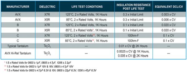
Because most of the test methods used to evaluate tantalum and ceramic capacitors differ significantly, a direct comparison of their relative performance is difficult to obtain through product literature and specification data. As a result, AVX performed the following tests to provide a more direct comparison of their performance.
6.2 Tantalum vs. Ceramic Comparative Testing
The AVX team chose ceramic and tantalum capacitor samples that have common ratings for both technologies and are commonly used in medical and other high-reliability applications.
- Tantalum Capacitor (TBCR106K016CRLB5000)
- 10μF, 16V
- 0805 case size
- 10μF, 16V
- 0805 case size
- X5R dielectric
- Ceramic Capacitor (MQ05YD106KGT1AN)
To ensure that special testing requirements (e.g., capacitance test frequency and DC Bias, hold times after environmental testing, etc.) could be accurately observed, collected, and compared for both basic product types, the team submitted all parts to the same test plan.
- Temperature Stability (MIL-PRF-55365) – 13 units
- Thermal Shock (MIL-STD-202 Method 107) – 40 units
- Moisture Resistance (MIL-STD-202 Method 106) – 40 units
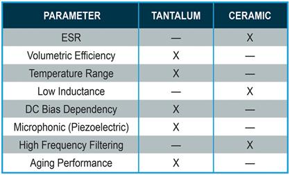
The majority of the test results showed that ceramic and tantalum capacitors performed similarly. Temperature stability, for example, revealed that ceramic capacitors are more stable in terms of equivalent series resistance (ESR) and DCL, while tantalum capacitors are more stable in terms of capacitance value over temperature. Tantalum capacitors also increased capacitance at elevated temperatures, whereas ceramic capacitors decreased capacitance at the same temperature. Furthermore, both moisture resistance and thermal shock testing resulted in stable performance for both technologies.
Ⅶ Why Use Tantalum Capacitors in Your PCB Design?
The tantalum capacitor has extremely high stability. The tantalum capacitor will maintain the expected capacitance better over a wide temperature and frequency range. With this stability, you get more of your PCB design’s expected behavior, which is especially important for filters; if the capacitance varies too much, you may lose the frequencies you want. Aside from the electrical differences, the tantalum capacitor’s construction makes it highly resistant to vibration issues, improving overall system reliability.
The preceding characteristics demonstrate how tantalum capacitors are uniquely suited to assist in modern electronics, but they are not without their quirks, and there are a couple of major ones to consider when designing these in. Tantalum capacitors are generally polarized devices, which means that their orientation must be carefully considered during PCB layout and assembly. This requires a little more work than a standard ceramic capacitor, but this is a characteristic of electrolyte base capacitors. When installing tantalum capacitors on a board, keep an eye out for their failure modes.
- How are tantalum capacitors constructed?
They consist of a tantalum metal anode, an oxide dielectric layer, and a conductive cathode. - What is the main disadvantage of using tantalum capacitors?
Their unfavorable failure mode can result in thermal runaways, fires, and small explosions. - Can tantalum capacitors be used in AC power applications?
No, they are unsuitable for AC power applications due to the required polarity. - What are the two main form factors available for tantalum capacitors?
They are typically available as leaded (through-hole) or surface mount (SMT) configurations. - Which standard is listed for tantalum capacitor manufacturing?
EIA 535, MIL PRF 39006, BS/DIN EN 130201, and BS EN 60384-24 are listed standards. - Why are tantalum capacitors preferred for surface mount assemblies?
They could withstand reflow soldering temperatures when aluminum electrolytics could not, offering high values in small packages. - How do tantalum and ceramic capacitors differ in temperature stability?
Tantalum capacitors are more stable in capacitance value over temperature, while ceramics are more stable in ESR and DCL. - What happens to tantalum capacitance at elevated temperatures?
Tantalum capacitors increase capacitance at elevated temperatures. - Are tantalum capacitors polarized devices?
Yes, they are generally polarized and must be connected to a DC supply with correct terminal polarity.