Greetings, welcome back. Today, we will demonstrate the process of creating a water level detector utilizing an Arduino Uno and water sensors. There are numerous water level sensor tutorials available online, but this method stands out. To begin with, let’s talk about the components required for creating a water level indicator and controller.
Component required to make water level indicator .
water sensors that can give output 3-5 volt when water is present -8
Light Emitting Diodes (LEDs) -4
arduino uno or similar
buzzer
jumper wires
Liquid Crystal Display (LCD)
motor
relay with power source
tip-122 NPN transistor
power source
To begin with, let’s talk about the water sensor. With the abundance of water sensors in the market, we have the option of using any sensor that outputs 1 when submerged in water. Due to the conductivity of water, supplying 5 volts to the bottom of the water will cause the respective conductive pins to go high when water reaches higher levels, thus detecting the presence of water.
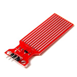
You may also opt to utilize water sensors as depicted in the figure below, which will generate 4.3 volts when fully immersed in water, indicating a digital electronic 1.

If you are not familier about other components please check arduino tutorials for beginners and you will learn something new before exploring other tutorial .
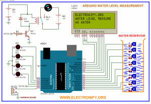
Okay now connect everythings as shown in circuit diagram and upload the code as shown in below and after that we will describe the code brifly .You can download the complete code , simulation file , from this link water level indication electronify.
WATER LEVEL MEASUREMENT USING ARDUINO UNO R3 AND WATER SENSORS (Code)
#include

LiquidCrystal lcd(13, 12, 11, 10, 9, 8);

byte sensorPin[] = {0,1,2,3,4,5,6,7};

byte ledPin[] = {17,16,15,14}; // number of leds = numbers of sensors

const byte sensors = 8;

const byte leds=4;

int motor = A4;

int buzzer = A5;

void setup()

{

for(int i = 0; i< sensors; i++) //initialize all sensor pins to input pin

{

pinMode(sensorPin[i], INPUT);

}

for(int i = 0; i< leds; i++) //initialize all led pins to output pins

{

pinMode(ledPin[i], OUTPUT);

}

pinMode(motor, OUTPUT);        //initialize motor pin to output pin

lcd.begin(20, 4);            //initializing 20x4 LCD

lcd.clear();                //clear LCD first

lcd.print("ELECTRONIFY.ORG");  // display string electronify.org

}

void loop()

{

int level = 0;

for(int i = 0; i < sensors; i++)

{

if(digitalRead(sensorPin[i]) == HIGH)

{

digitalWrite(ledPin[i/2], HIGH);

level = i+1;

} else

{

digitalWrite(ledPin[i/2], LOW);

}

}

lcd.setCursor(0,1);

lcd.print("WATER LEVEL MEASURE");

lcd.setCursor(0,2);

switch(level) {

case 1:

lcd.print("LEVEL 1");

digitalWrite(motor, HIGH);

break;

case 2:

lcd.print("LEVEL 2");

digitalWrite(motor, HIGH);

break;

case 3:

lcd.print("LEVEL 3 ");

digitalWrite(motor, HIGH);

break;

case 4:

lcd.print("LEVEL 4 ");

digitalWrite(motor, LOW);

break;

case 5:

lcd.print("LEVEL 5 ");

digitalWrite(motor, LOW);

break;

case 6:

lcd.print("LEVEL 6 ");

digitalWrite(motor, LOW);

break;

case 7:

lcd.print("LEVEL 7 ");

digitalWrite(motor, LOW);

break;

case 8:

lcd.print("LEVEL 8 ");

digitalWrite(motor, LOW);

lcd.setCursor(0,3);

lcd.print("WARNING : OVERFLOW");

for(int j = 0; j< 255; j++)

{

analogWrite(buzzer, j);

delay(10);

}

break;

default:

lcd.print("NO WATER");

digitalWrite(motor, HIGH);

break;

}

delay(50);

}
WATER LEVEL MEASUREMENT USING ARDUINO UNO R3 AND WATER SENSORS (Schematic Diagram)
Short Description
To begin with, let’s talk about the water sensor. With the abundance of water sensors in the market, we have the option of using any sensor that outputs 1 when submerged in water. Due to the conductivity of water, supplying 5 volts to the bottom of the water will cause the respective conductive pins to go high when water reaches higher levels, thus detecting the presence of water.
You may also opt to utilize water sensors as depicted in the figure below, which will generate 4.3 volts when fully immersed in water, indicating a digital electronic 1.

