Summary of 26-Way MIDI DRUMS
Summary: A 26-key drum pad MIDI/USB interface using an Arduino Mega converts 16 piezo velocity inputs (0–127) and 10 fixed-velocity switches into MIDI notes. Drums are mapped in software (typically MIDI channel 10), and outputs go to a MIDI 5-pin DIN. The unit requires external piezos, resistors, diodes, capacitors, switches, and a 9V DC supply; unused analog inputs must be grounded to avoid noise.
Parts used in the 26-Way MIDI DRUMS:
- Arduino Mega board with pre-programmed Atmega microcontroller
- 2.1mm power socket
- Power indicator LED
- 16 piezo-electric transducers (external)
- 32 × 1 MOhm resistors
- 16 × IN4148 diodes
- 16 × 100 nF capacitors
- 10 push-to-make momentary switches
- MIDI 5-pin DIN output socket
- 9V battery or equivalent DC power source
His creation is a 26-key drum pad setup that combines MIDI and USB connectivity, featuring a fixed velocity byte for 10 drum switches alongside a 16-key velocity-sensitive circuit. This system utilizes piezo sensors to achieve a complete velocity range from 0 to 127. The drums are already chosen to be sent to the MIDI outputs 35-50 for the piezos and 51-60 for the switches. General MIDI drums offer a variety of MIDI drum options to choose from.
It provides MIDI data which has to be sent to a drum/synthesiser or sound module. The velocity byte is dependent on how hard the piezo transducer is hit. The drum choices, and the MIDI transmit channel are assigned in the program. However, normally the drum sounds are assigned to MIDI channel 10.
The 26-Way drum inputs to MIDI Output unit utilizes:
|
The 26-Way drum inputs to MIDI Output unit requires:
- A 9v battery or equivalent DC power source,
- The circuit consists of the MIDI drum interface.
- Suitable external 16 piezo-electric transducers,
- 32 off 1M Ohm resistors
- 16 off IN4148 diodes,
- 16 off 100 nF capacitors,
- Suitable 10 push-to-make switches
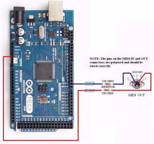
Circuit Schematic:
A circuit schematic of the MIDI drum interface shows the Input/Output connections. The circuit schematic for the Arduino MEGA is also available.
NOTE: Any unused analog inputs should be connected to ground (GND) otherwise they will pick up noise and produce spurious outputs.
MIDI:
It supplies MIDI information that must be transmitted to a drum machine/synthesizer or audio module. The speed byte is determined by the force applied to the piezo transducer. The program assigns the drum choices and the MIDI transmit channel. Typically, the drum sounds are usually mapped to MIDI channel 10.
For more detail: 26-Way MIDI DRUMS
- How many velocity-sensitive inputs does the project have?
It has 16 velocity-sensitive inputs providing a full 0–127 velocity range. - How many fixed-velocity switch inputs are included?
There are 10 momentary action switches that output a fixed velocity byte. - Which microcontroller board is used in the project?
An Arduino Mega board with a pre-programmed Atmega microcontroller is used. - What components are required for the piezo input conditioning?
The design requires 32 1 MOhm resistors, 16 IN4148 diodes, and 16 100 nF capacitors for the piezo inputs. - What power source does the unit require?
The unit requires a 9V battery or equivalent DC power source via a 2.1mm power socket. - Where are the MIDI drum outputs sent?
Piezo-triggered drums are sent to MIDI outputs 35–50 and switch-triggered drums to 51–60 as chosen; generally drums map to MIDI channel 10. - What must be done with unused analog inputs?
Any unused analog inputs should be connected to ground to prevent noise and spurious outputs. - What type of MIDI connector is provided on the unit?
The unit provides a MIDI 5-pin DIN output socket.