Summary of Wall-E Robot Arduino EasyVR3 (Updated) New Video With Voice Commands..Funny!)
This article details a DIY project to transform a Wall-E toy robot into a voice-controlled Arduino-based bot. The author guides readers through stripping the toy, installing six servos for movement, and integrating an EasyVR3 module for voice recognition. Key steps include modifying the plastic shell, wiring electronics like the Arduino Nano and servo shield, and programming voice commands using EasyVR Commander and Quick Synth software.
Parts used in theWall e Robot:
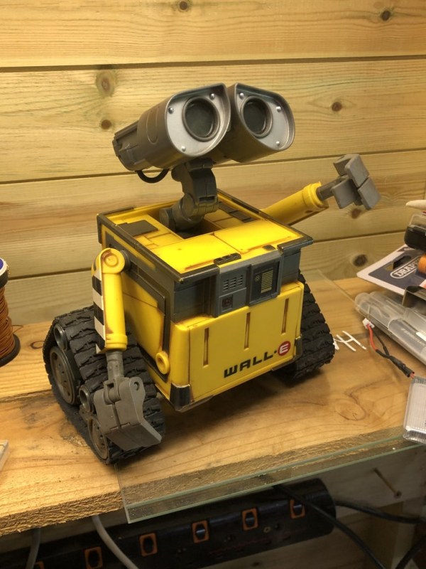
- Wall e plastic toy model with blue LED eyes
- EasyVR3 Voice Recognition Module
- Arduino Nano
- Arduino Nano Servo Shield
- 2 x 360deg Servos
- 3 x Servos with metal gears
- 2 x micro servos with metal gears
- 9v Batteries
- Quick USB Adapter cable
- Sharp IR Sensor
- Micro on/off switch
Whilst looking through videos on Youtube one day(Like you do) I came across a video with a Diy Arduino based Wall e, I thought wow! what a brilliant idea, I didn’t at that time even know what Arduino was so I began looking into it.
I wanted to have a go at building one of these awesome little robots, just to look at them brings a smile to my face and I’m no kid believe me, then I watched the movie and that intrigued me even more.
I think that was the start of me getting to know more about Arduino and then actually seriously thinking about building a Wall e, everything looked so complicated, actually cutting a Wall e up in the first place looked a bit daunting, then the electrical part of it as well, Servo’s??? what’s a Servo, what do they do? Anyway that was back then(It was a couple of years ago:)). With a lot of patience and time I finally got a functional Wall e robot which could do what I wanted it to do(Sometimes).
There are quite a few videos of Wall e Robots on Youtube etc and there are also various tutorials as well, let me show you how I make these Wall e robots, the build is pretty much straight forward(Which is easy for me to say now) we are stripping out the internals of the Wall e and replacing with 6 Servos and some Electronics, the complicated part to this Robot is when using the Easyvr3 Voice recognition is the code, and how you get to it.
My build is loosely based on a Robot by DIY(makers) on Youtube, there is a link to their website, it is in Spanish but can be Translated, there are step by step photos of the build so I wont go into too much detail in this Instructable, mine is more or less the same with Servo installation so I will focus more on the electronics and code, but with a few pointers along the way with the build.
My Wall e build is Arduino Nano based and its used in conjunction with a Nano Servo shield and EasyVR3 Voice recognition module, the idea being that you will give Voice commands and Wall e will carry out the commands.
As for the Arduino code, this code is driven by the EasyVR3 module using EasyVR Commander, this software allows you to input voice commands then it turns these commands into code and in turn uses actions for the movements, it also allows you to input the Wall e sounds using another piece of EasyVR software called Quick Synth, these sounds can be called up simultaneously with the actions.
I wont be uploading the Arduino code at the end of this Instructable there is little point, the code is generated within the EasyVR software and would only work with my voice, I will give good guidance with Screen shots on how the code is generated using the EasyVR Commander and Quick Synth software, and also using Audacity to change the format of MP3’s.
So we are agreed that the code is unique only for your bot as it will only recognise your voice and the commands you have given it in the code, my hope in this Instructable is to show you how I approached the build of this Wall e, there is a fair bit of cutting of plastic etc to house the Servos, and a very small cavity for all the components so using the Nano and servo shield is an ideal solution to this problem, ideally the Wall e should be purchased as one listed for parts etc and ideally it should be the model with the blue Led eyes, after this build it can not be put back to its original format.
There is one action with the Wall e where I have come unstuck, I cannot input a Object avoidance sketch into the actions within the code, if anyone knows how to do this then please let me know, but as for everything else, it does what it says on the tin.
This is quite a costly build with the EasyVR3 module bumping the cost up significantly.
Its quite a lengthy Instructable so lets get started:
Instructable updated 02.07.2021 Video uploaded showing various Voice commands..
Instructable updated 05.07.2021 with more build photos.
Instructable updated 10.07.2021 with more photos of the final stages.
All music Tracks are Copyright free courtesy of Audionautixs.com..Jason Shaw
Supplies
Wall e plastic toy model as described 7″ tall(Blue LED eyes)
EasyVR3 Voice Recognition Module, without the shield
Arduino Nano
Arduino Nano Servo Shield
2 x 360deg Servos(For the Tracks)
3 x Servos ideally with metal gears(Arms and Horizontal head movement)
2 x micro servos(Metal Gears)(Vertical head movement)
9v Batteries
Quick USB Adapter cable
Sharp IR Sensor(Optional)
Micro on/off switch
Tools etc
Dremel
Hot glue gun
CA Glue
Tweezers
Soldering Iron
Solder
Heat Shrink
Step 1: Preparation and Base Servo Installation
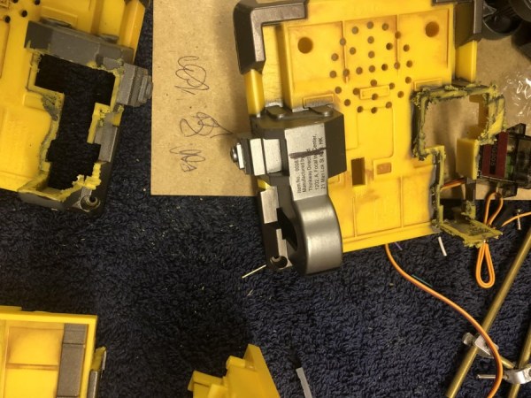
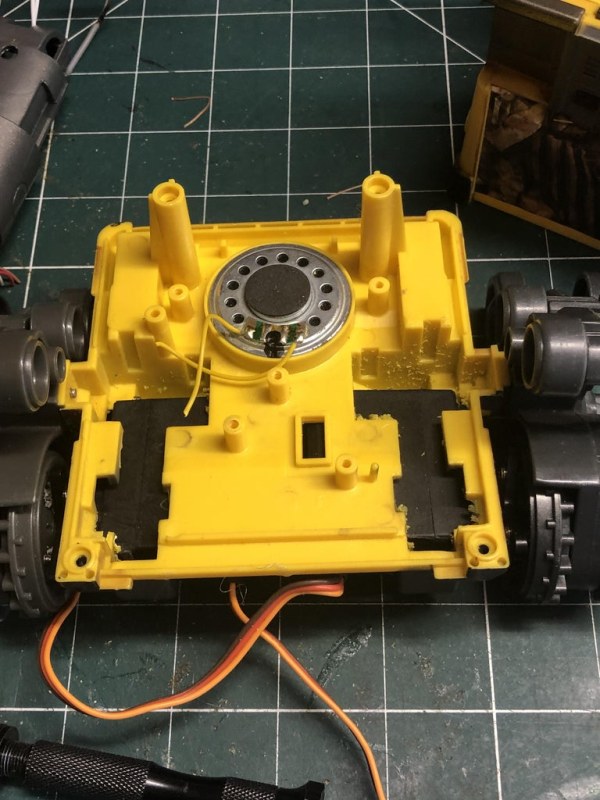
The Wall e has to be completely stripped of all its components, Tracks and drive train removed, at the the end of this there will be 4 main components, the base, the body, the top part and the head and neck module,
If we start with the base, we have to remove the drive train, cut through the Axle flush with the drive train wheel, then cut away the plastic to leave a flat surface to house the 2 x 360 degree servo’s for the tracks, pay attention to how the drive train will be aligned up to the servos, this is crucial!
The cutting doesn’t have to be perfect when installing the Servos, the Servos are held in place using Hot Glue and this fills any gaps you may have.
The cross shaped servo adapter is mounted centrally to the drive train wheel using 4 small screws, use a small drill to pilot the holes first.
Once the the drive trains are pushed onto the Servo, we can insert the Screw through the mounting holes in the body and secure the drive train to the base(See Photo)
The bottom section Servo fitment is now complete, the servo cables will need to be cut and soldered as they are too long, or they can be coiled and secured adjacent to the Servos and hot glued in place, with space being at a premium I shortened, and soldered, use heat shrink to isolate and protect the cables.
When the Wall e was taken apart, you will have noticed a speaker in the base, we will use the same speaker for sounds generated from the Easyvr module.
Step 2: The Top Section Servo Installation
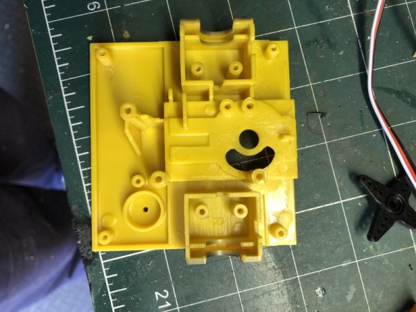
Much the same as the base of the Wall e the next stage is to remove plastic so we can install the servos for arm movement and horizontal head movement.
Align the Servos as in the photos and hot glue in place.
There is some cutting out needed to install the head horizonal servo, and be sure to leave provision at the back of the neck area to allow for the cables from the head to go into the body.
I leave the Servo cables at full length as the top section needs to be removed to allow access to the Voice recognition module to re-program with the Quick USB Adapter cable.
I install the microphone into the top part of the body as well, some of the tops have a recess with a hole, some have a black plastic square, depending on which Wall e you have.
We can now move onto the head servo:
Update:
Added some more photos of the build, and additionally for the Wall_E Arm and Horizontal head Atachments, Ideally we need to use a round Servo horn/adapter, I found some for a previous build but had to design and 3D print 3, STL file is attached if anyone wants to print some, these will only fit MG90S Micro Servos, the ones I have used have metal gears and spline, no holes in the round adapter as I don’t use them ,apart from the hole to screw it onto the Servo.
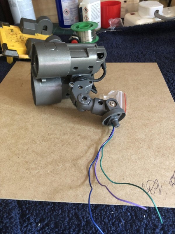
Step 3: Wall E Head/Eye Servo Installation
First job with the head section is to remove the neck section, be careful pulling the wires out from the LED’s we then clip off the original rubber dummy cables and remove the plastic holding pieces attaching the head to the central connector rod.(See photos for clarity) we can leave the metal rod in position but its not used and I have one Wall e with it in place and one with it removed.
Now undo the securing screws on both sets of eye component back section and remove the back part of the eye body this is in 2 sections per eye module again be careful with the LED wires.
I came across an issue, I was checking to see if the LED’s for the eyes worked, they did for a Nano second, I put 5volts through them and I suspect that they were 3v D’oh! anyway I had some 5v blue Led’s so just removed the old and in with the new, these are just held in with a dab of hot glue.
One of my Wall e builds didn’t have the LED’s for the eyes so I used some blue masking tape, and a couple of 5v blue led’s, It did the trick
We now have to cut more plastic so the Servo fits inside this section, Micro servos are used for this process, half metal gears are the Servos I use.
Rather than explain, look at the photos, which show in detail what needs to cut, this whole operation is a very tight fit, hot glue or CA glue is used to hold top and bottom sections together once the Servo’s are installed.
The cables from the LED’s are routed over the top of the Servos and go out through the back, LED cables through one section and the Servo cable, we need to either install a dummy servo or make a dummy servo for one of the eye sections as only 1 Servo is used but 2 servo arms are there to keep things aligned.
Please be aware that with the Servos installed, its a bit of a chore trying to get everything back in place, so I cut of the mounting lugs and and used drops of CA glue to hold in place.
The neck angle needs to have some plastic removed, the servo horns from the head section need to fit into this cavity, I just pumped some hot glue in to secure, this did the trick as well.
I cut the the little tabs off the bottom of the neck section, threaded the cables in the space behind the neck and then initially during servo tests, fitted a round servo adapter and I just held in place with double sided tape, Then when satisfied with Servo angles, I used a screw to secure the neck in position with a dab of CA glue.
Step 4: Installing the Electronics in the Wall E
In this section we cover the electronics installation.
We need an Arduino Nano, be careful with some of the Arduino Nano clones when you are trying to download code, some have the old bootloader installed, as mine did and this needs to be checked for the code to be downloaded.
Prior to installing the Nano to the base, I soldered a 9v Battery connector to the under side of the power connector, in turn the power side of the cable will have a Micro on/off switch this is fitted to the rear of the Wall e Body.
I’m using 9v Rechargeable batteries for my Wall e’s The batteries I use have micro usb connectors and makes charging really easy, they came in a pack of 4 and 4 can be charged at the same time.
The Arduino Nano is attached to the Nano Servo shield, this shield is great for our purpose as it only has a small footprint and space is at a Premium, with the speaker already in place and held in place, I use the left hand speaker cover screw hole to secure the Nano and shield, (this leaves ample room to the right hand side for the 9v Battery), the usb connector on the nano needs to be at the rear of the wall e for ease of programming, and you do need to re-program quite a few times initially to get things right, especially Servo alignment.
As for the EasyVR3 installation, I used some double sided tape and placed this to the front inside panel with the Quick USB connector pointing up, again, good access is needed as there are numerous code changes during initial testing.
So no one gets confused here, The Voice commands and actions code are programmed using the EasyVR3 Commander software using the Quick USB 6 pin connector, The QuickSynth 5 software is used to input sounds into the EasyVR Commander through the same cable and these sounds are used simultaneously with the actions to move the Servos.
So the Arduino code is generated by EasyVR3 Commander, we then add servos to the code along with voice commands etc and then the final code is sent to the Wall e via the Arduino Nano….Phew! I hope I’m making sense here, I had to walk away a few times during the first build to get my head straightened out 🙂
That’s basically the hardware installed, the connections can now be made.
Step 5: Making the Connections.
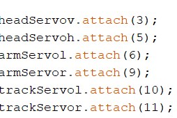
Unfortunately I don’t have the necessary software to sketch a wiring diagram, buts its pretty straight forward, you assign a digital pin on the Arduino Nano shield to a particular Servo as in the screen shot.
On the Servo Shield the Pin numbers relate to the Nano pins, making servo connections easy, You already have the 3 way female connector on the servo cable, ensure you have it the right way round and push them onto the relevant pin numbers on the shield, Job done.
Head Vertical Servo is Pin 3
Head Horizontal Servo Pin 5
Left arm Servo Pin 6
Right arm Servo Pin 9
Left Track Servo Pin 10
Right Track Servo Pin 11
The LED’s for the Eyes are Pin 2
Join the cables from the LED’s in the eyes and fit female dupont connectors, again the shield makes for an easy connection as the – and + are adjacent to the S data pin.
I did fit an IR Sensor, but its not in use, if you want to fit IR sensors just assign an Analogue pin to each Sensor, picking up + and – on the shield.
With the micro switch, split the positive and solder the ends to the switch, this simply breaks the connection from the battery, I created a slot for the micro switch, and used CA glue to secure.
The connections from the EasyVR3 are TX and RX to pins 12 and 13 on the Nano pick up a 5v and ground from the shield to power the EasyVR3 I soldered 4 Pins to the EasyVR as I’m using female dupont connectors.
That’s the connections complete.
Step 6: EasyVR3 Programming

Download The commander software and The Arduino software for the Easyvr as well
Connect the Quick USB connector to the EasyVR and open up The commander software.
Press the connect Tab if it doesn’t connect it will say the bridge needs updating.
In the Arduino EasyVR examples you will find the bridge settings, update these and try to connect again.
With connections made, we can now add our voice commands.
The first thing we do is add a Trigger, this trigger will wake Wall e up, the default is Robot, I’ve used Wake up or Wall e wake up, you can make it what you want, call it a password if you will to get things started.
For this Instructable I will use the trigger Wall e wake up!
Highlighting the trigger tab in the left hand column, now if you run your mouse along the top there are some speech bubbles, find the one that says (Add Command) this will now create another text box below where it says trigger, in this box type your trigger word, In this case its Wall e wake up, now we have to train that command, ensure the Wall e Wake up text box is blue, if its not, click within it to highlight it, then run along the speech bubbles and hover over the one that says train command, click on this and follow the instructions, press speak now and say the words in the box clearly, phase 1 and phase 2 the same words twice.
The same rules apply to the word commands, click on Index 1 Group and again find the add command speech bubble, and populate the text box with any commands you want wall e to perform, bearing in mind you have to write the code to do this, we are making servos move to voice commands and adding the Wall e recordings as well within the code, This comes later.
The software lets you know if there is something wrong when you voice the words in the text boxes when training voice commands.
Once you have all the voice commands you want, there is another tab along the top row which says (Test Group)
Click on this and say any of the words you have just trained, the spoken word will turn a light green and flash a few times, you have to click on it several times to go through the whole group.
Now we have our voice commands we can now add some Wall e sounds:
Source: Wall-E Robot Arduino EasyVR3 (Updated) New Video With Voice Commands..Funny!)
- How is the code generated for this project?
The code is generated within the EasyVR Commander software which converts voice commands into actions. - Can I put the Wall e back to its original format after building?
No, after this build it cannot be put back to its original format because parts are cut and modified. - What software is used to input sounds for the robot?
Quick Synth software is used to input sounds that can be called up simultaneously with the actions. - Which pins are assigned to the track servos?
The Left Track Servo is assigned to Pin 10 and the Right Track Servo is assigned to Pin 11. - What happens if the EasyVR bridge does not connect initially?
You must update the bridge settings found in the Arduino EasyVR examples and try connecting again. - How do you train a new voice command in the software?
You highlight the text box, hover over the train command speech bubble, click speak now, and repeat the words twice. - Is the object avoidance sketch included in the final code?
No, the author could not input an object avoidance sketch into the actions within the code. - What type of battery connector was soldered to the power connector?
A 9v Battery connector was soldered to the underside of the power connector.