Summary of Utilizing the W5300 TOE Shield with Arduino IDE and STM32 Nucleo-F429ZI: A Comprehensive Guide
This guide explains how to use the W5300 TOE Shield with the STM32 Nucleo-F429ZI via the Arduino IDE, covering IDE setup, library installation, hardware wiring, Ethernet verification, and connecting to the Beebotte cloud to control an LED remotely using MQTT over Ethernet.
Parts used in the W5300 TOE Shield with Nucleo-F429ZI Project:
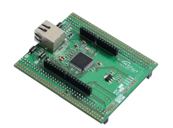
- W5300 TOE Shield
- STM32 Nucleo-F429ZI Board
- LED
- 5-pin cable (to connect Nucleo to PC)
- Ethernet cable
- PC running Arduino IDE
Narrative
0. Preface
This guide is dedicated to instructing you on the utilization of the W5300 TOE Shield in tandem with the Arduino IDE, particularly when paired with the STM32 Nucleo-F429ZI board. Within this document, we shall furnish a comprehensive, step-by-step tutorial encompassing the configuration of the Arduino IDE, establishment of hardware connections, and validation of Ethernet functionality. Additionally, we will demonstrate the process of linking the W5300 TOE Shield to the Bee botte cloud platform, empowering you to seamlessly transmit and receive data across global boundaries.
The W5300 TOE shield serves as a hardware module, tailored for employment with Arduino-compatible boards, designed to deliver network connectivity. This specialized chip streamlines the intricacies of TCP/IP communication, thereby facilitating swift and efficient data exchange over Ethernet channels. On a parallel note, Beebotte stands as a cloud-centric platform offering real-time data management and communication solutions for interconnected devices and applications. Its capabilities empower developers to construct and manage IoT applications adept at aggregating, processing, and responding to data sourced from sensors, actuators, and other interconnected devices.
1. Element
In order to employ the W5300 TOE Shield within the Arduino IDE environment, it necessitates the utilization of the STM Nucleo F429ZI board. Compatibility with other boards is currently pending.
Physical Components
- W5300 TOE Shield
- STM32 Nucleo-F429ZI Board
- LED
Software
- Arduino IDE
- Beebotte Cloud
2. Utilizing the W5300 TOE Shield in Arduino IDE
2.1. Setting Up the Arduino IDE
1) Incorporate Libraries
Download the Wiznet/W5300-TOE-Arduino repository from here.

2) Integrate Libraries
Download this repository Wiznet/W5300-TOE-Arduino.
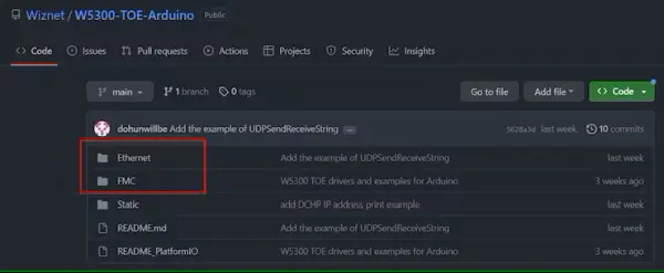
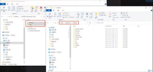
Copy the Ethernet and FMC folders from the repository, and then paste them into the designated directory on your computer:C:
C:\\Users_YOUR_NAME_\\AppData\\Local\\Arduino15\\libraries
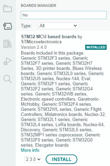
3) Install board manager
nstall “STM32 MCU based boards” in the Board Manager of the Arduino IDE.
2.2 Verification
Although not mandatory, this step offers an option to verify the proper functioning of Ethernet. You have the flexibility to bypass this stage if desired.
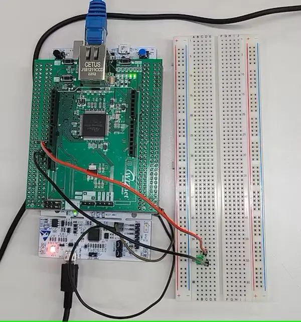
1) Connect hardware
Assemble the W5300 TOE Shield with the Nucleo board. Establish a connection between the Nucleo board and your PC using a 5-pin cable, and subsequently link the W5300 TOE Shield to an Ethernet cable.
2) Upload
Navigate to Tools > Board and select “Nucleo-144” from the list of board options
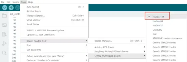
Subsequently, navigate to the section labeled “Board part number” and opt for “Nucleo-F429ZI” from the available choices.
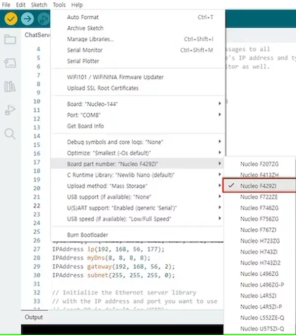
After following the preceding instructions, you’ll discover Nucleo-144 examples within the Arduino IDE’s “Examples” section. To validate the proper functionality of Ethernet, we will proceed by loading the basic Chat Server example and conducting a test.
Presently, access the Tools menu and proceed to the Port section. Choose the port linked to the board, and to conclude, initiate the upload of the file.
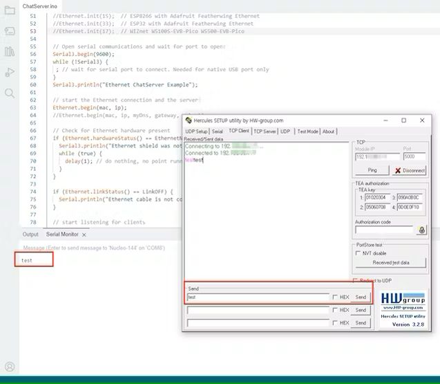
3) Test in Terminal program
To validate the connection, you can employ the Hercules terminal program. Launch Hercules and navigate to the TCP Client tab. Here, input the designated IP address and port number. Successful establishment of the connection should result in the display of an echo message within Hercules upon sending a message. Furthermore, you can observe the transmitted message in the serial monitor as well.
3. Connect to Cloud
3.1. Create dashboard
Upon establishing a connection with Beebotte, proceed to click the “Create New” button, which will direct you to the channel creation page. Here, configure the board name along with the resource’s name and type that you intend to utilize, subsequently generating the channel.
Following the channel’s creation, you have the ability to access and verify the associated token. Be sure to copy and store this token for future reference and application.
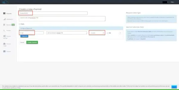
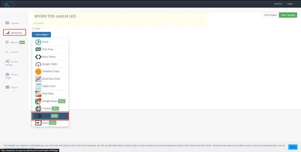
Once the dashboard has been established, proceed to incorporate an ON/OFF widget. Designate the resource of this widget to correspond with the LED feature of the Nucleo-F429ZI board.
3.2. Connect LED
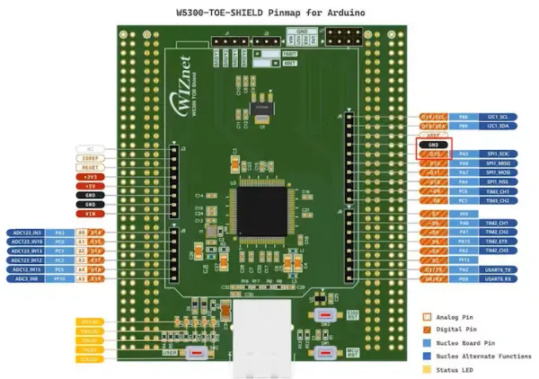
Establish a connection between the LED and the W5300 TOE Shield by attaching the positive (+) terminal of the LED to the D13 pin, and connecting the negative (-) terminal to the ground pin. For additional details, consult the Arduino pin map provided by the W5300-TOE-Shield.
3.3. Upload file
Adjust the LED pin designation to 13, and substitute the token with the copied token value obtained earlier. Furthermore, replace the channel name within the code snippet with the name of the channel you established.
#define LEDPIN 13  // Pin which is connected to LED.

#define TOKEN "token_jw9p00M4f7b7pqxP"  // Set your channel token here

#define CHANNEL "NucleoF429ZI"  // Set your channel name
#define LED_RESOURCE "led"
The preceding code initially employed the Beebotte MQTT Domain name; however, due to DNS issues, it was reconfigured to establish an IP-based connection. You are required to update all the values, with the exception of g_target_ip, to align with your specific network configuration.
byte mac[] = {0xDE, 0xAD, 0xBE, 0xEF, 0xFE, 0xED};
byte g_target_ip[] = {54, 221, 205, 80};
IPAddress ip(192, xxx, xxx, xxx);
IPAddress myDns(xxx, xxx, xxx, xxx);
IPAddress gateway(xxx, xxx, xxx, xxx);
IPAddress subnet(xxx, xxx, xxx, xxx);
Upon successfully uploading the code onto the board, you gain the ability to manage the LED status through cloud-based control. A video demonstrating this functionality is provided below. By interacting with the widget, you can observe the LED toggling between the on and off states.
#include <SPI.h>
#include <Ethernet.h>
#include <PubSubClient.h>
#include <ArduinoJson.h>
#include "HardwareSerial.h"

#define LEDPIN 13 // Pin which is connected to LED.

//#define BBT "54.221.205.80"         // Domain name of Beebotte MQTT service
#define TOKEN "token_xxxxxxxxx"  // Set your channel token here

#define CHANNEL "NucleoF429ZI"  // Replace with your device name
#define LED_RESOURCE "led"

// Enter a MAC address of your shield
// It might be printed on a sticker on the shield
byte mac[] = {0xDE, 0xAD, 0xBE, 0xEF, 0xFE, 0xED};
byte g_target_ip[] = {54, 221, 205, 80};
IPAddress ip(000, 000, 000, 000);
IPAddress myDns(000, 000, 000, 000);
IPAddress gateway(000, 000, 000, 000);
IPAddress subnet(000, 000, 000, 000);

EthernetClient ethClient;
PubSubClient client(ethClient);

// to track delay since last reconnection
long lastReconnectAttempt = 0;

const char chars[] = "abcdefghijklmnopqrstuvwxyzABCDEFGHIJKLMNOPQRSTUVWXYZ1234567890";

char id[17];

const char* generateID() {
  randomSeed(analogRead(0));
  int i = 0;
  for (i = 0; i < sizeof(id) - 1; i++) {
    id[i] = chars[random(sizeof(chars))];
  }
  id[sizeof(id) - 1] = '\0';

  return id;
}

// will be called every time a message is received
void onMessage(char* topic, byte* payload, unsigned int length) {

  // decode the JSON payload
  StaticJsonDocument<256> doc;

  // Test if parsing succeeded
  auto error = deserializeJson(doc, payload);
  if (error) {
    Serial.print(F("deserializeJson() failed with code "));
    Serial.println(error.c_str());
    return;
  }

  // led resource is a boolean read it accordingly
  bool data = doc["data"];

  // Print the received value to serial monitor for debugging
  Serial.print("Received message of length ");
  Serial.print(length);
  Serial.println();
  Serial.print("data ");
  Serial.print(data);
  Serial.println();

  // Set the led pin to high or low
  if (data == 0) {
    digitalWrite(LEDPIN, LOW);
  } else if (data == 1) {
    digitalWrite(LEDPIN, HIGH);
  }
  // digitalWrite(LEDPIN, data ? HIGH : LOW);
}

// reconnects to Beebotte MQTT server
boolean reconnect() {
  if (client.connect(generateID(), TOKEN, "")) {
    char topic[64];
    sprintf(topic, "%s/%s", CHANNEL, LED_RESOURCE);
    client.subscribe(topic);

    Serial.println("Connected to Beebotte MQTT");
  }
  return client.connected();
}

void setup() {
  pinMode(LEDPIN, OUTPUT);

  client.setServer(g_target_ip, 1883);
  client.setServer(BBT, 1883);
  // Set the on message callback
  // onMesage function will be called
  // every time the client received a message
  client.setCallback(onMessage);

  // Open serial communications and wait for port to open:
  Serial3.setRx(PC11);
  Serial3.setTx(PC10);
  delay(50);
  Serial.begin(9600);
  while (!Serial) {
    ;  // wait for serial port to connect. Needed for native USB port only
  }

  // Ethernet.init(17);

  // start the Ethernet connection:
  if (Ethernet.begin(mac) == 0) {
    Serial.println("Failed to configure Ethernet using DHCP");
    // try to congifure using static IP address instead of DHCP:
    // Feel free to change this according to your network settings
    // IPAddress ip(192, 168, 56, 177);
    Ethernet.begin(mac, ip, myDns, gateway, subnet);
  }
  // give the Ethernet shield a second to initialize:
  delay(1000);
  Serial.println("connecting...");
  lastReconnectAttempt = 0;
}

void loop() {
  if (!client.connected()) {
    // Serial.println("NOT CONNECTED");/
    long now = millis();
    if (now - lastReconnectAttempt > 5000) {
      lastReconnectAttempt = now;
      // Attempt to reconnect
      if (reconnect()) {
        lastReconnectAttempt = 0;
      }
    }
  } else {
    // Client connected
    // Serial.println("CONNECTED");/
    client.loop();
  }
}
- What boards are required for using the W5300 TOE Shield in this guide?
The guide requires the STM32 Nucleo-F429ZI board; compatibility with other boards is pending. - How do I install the W5300 libraries into the Arduino IDE?
Download the Wiznet/W5300-TOE-Arduino repository, copy the Ethernet and FMC folders into C:Users_YOUR_NAME_AppDataLocalArduino15libraries. - Which board package must be installed in the Arduino IDE Board Manager?
Install STM32 MCU based boards in the Board Manager. - How do I verify the Ethernet connection after uploading example code?
Use the Chat Server example, then open Hercules TCP Client with the board IP and port; send a message and expect an echo and serial monitor output. - How is the LED physically connected for cloud control?
Connect the LED positive to D13 and the negative to ground on the shield/Nucleo per the W5300-TOE-Shield Arduino pin map. - How do I configure Beebotte for this project?
Create a channel with a resource for the device, copy the channel token, and add an ON/OFF widget mapped to the LED resource. - What code values must I update before uploading to the board?
Set LEDPIN to 13, replace TOKEN and CHANNEL with your values, and update IP, DNS, gateway, and subnet values except g_target_ip. - Why was the Beebotte domain replaced in the example code?
Due to DNS issues the example was reconfigured to use an IP-based connection for the Beebotte MQTT service.