Summary of Using Arduino as an ISP: Burning Bootloaders onto AVR Microcontrollers
This article explains how to use an Arduino as an ISP to burn bootloaders onto AVR microcontrollers. It covers uploading the ArduinoISP sketch, wiring the Arduino to the target AVR, installing Arduino IDE and necessary libraries, adding third-party board support (e.g., MiniCore for ATmega8), selecting Arduino as programmer, burning the bootloader, and testing by programming the MCU (using Arduino as USB-TTL) with a Blink sketch.
Parts used in the Arduino as ISP Bootloader:
- Arduino Uno (or compatible Arduino board)
- Target AVR microcontroller (example: ATmega8)
- USB cable for Arduino
- Jumper wires for MOSI, MISO, SCK, RESET, VCC, GND
- LED and resistor (for heartbeat/error/programming indicators, optional)
- Computer with Arduino IDE installed
- USB-to-TTL adapter (for programming target after bootloader)
- Required Arduino libraries (Wire, Dallas Temperature, LiquidCrystal, DHT)
Introduction
At times, incorporating AVR microcontrollers into electronic projects becomes necessary. However, beginners might encounter challenges in comprehending the process of uploading or burning code onto an AVR IC. Burning bootloaders onto AVR microcontrollers can be facilitated with the assistance of an Arduino board, particularly when alternative programming hardware is unavailable. Additionally, utilizing Arduino as an ISP proves beneficial for the creation and evaluation of AVR programs. Hence, this article delves into utilizing Arduino as ISP to burn bootloaders onto AVR microcontrollers.
To initiate the bootloader burning process, it’s crucial to establish the correct connections between the Arduino board and the AVR microcontroller, which is thoroughly discussed in this article alongside detailed, step-by-step instructions. Let’s delve straight into the process!
Arduino as ISP Bootloader?
Arduino boards have the capability to serve as In-System Programmers (ISP) for burning bootloaders onto AVR microcontrollers. Bootloaders, small programs that initiate when a microcontroller starts, enable programming over a serial connection without requiring external programming hardware.
To employ an Arduino board as an ISP, it’s necessary to upload the ArduinoISP sketch onto the Arduino board. This sketch incorporates the firmware essential for the Arduino board to function as an ISP. Once the sketch is successfully uploaded, the Arduino IDE can be utilized to burn the bootloader onto the AVR microcontroller.
Hardware Components
To utilize Arduino as an ISP for burning bootloaders onto AVR microcontrollers, you’ll need the following hardware components.
Arduino ISP Bootloader
To employ Arduino as an ISP for burning a bootloader onto an AVR microcontroller, adhere to the provided steps:
Schematic
Establish connections as per the provided circuit diagram.
Installing Arduino IDE
Initially, you’ll want to download the Arduino IDE software from the official Arduino website. Below is a straightforward, step-by-step tutorial on how to install Arduino IDE.
Installing Libraries
Before initiating the code upload process, ensure to download and extract the specified libraries to the default location at /Progam Files(x86)/Arduino/Libraries. This step is crucial for integrating the sensor seamlessly with the Arduino board. Below, you’ll find a straightforward guide detailing “How to Add Libraries in Arduino IDE.”
1. Wire bus
2. Dallas Temperature
3. LiquidCrystal
4. DHT
Code
Please proceed by copying the provided code and uploading it to the Arduino IDE software.
/*
Made on 18 may 2021
Home
based on Arduino Library
*/
// ArduinoISP
// Copyright (c) 2008-2011 Randall Bohn
// If you require a license, see
// http://www.opensource.org/licenses/bsd-license.php
//
// This sketch turns the Arduino into a AVRISP using the following Arduino pins:
//
// Pin 10 is used to reset the target microcontroller.
//
// By default, the hardware SPI pins MISO, MOSI and SCK are used to communicate
// with the target. On all Arduinos, these pins can be found
// on the ICSP/SPI header:
//
// MISO °. . 5V (!) Avoid this pin on Due, Zero…
// SCK . . MOSI
// . . GND
//
// On some Arduinos (Uno,…), pins MOSI, MISO and SCK are the same pins as
// digital pin 11, 12 and 13, respectively. That is why many tutorials instruct
// you to hook up the target to these pins. If you find this wiring more
// practical, have a define USE_OLD_STYLE_WIRING. This will work even when not
// using an Uno. (On an Uno this is not needed).
//
// Alternatively you can use any other digital pin by configuring
// software (‘BitBanged’) SPI and having appropriate defines for PIN_MOSI,
// PIN_MISO and PIN_SCK.
//
// IMPORTANT: When using an Arduino that is not 5V tolerant (Due, Zero, …) as
// the programmer, make sure to not expose any of the programmer’s pins to 5V.
// A simple way to accomplish this is to power the complete system (programmer
// and target) at 3V3.
//
// Put an LED (with resistor) on the following pins:
// 9: Heartbeat – shows the programmer is running
// 8: Error – Lights up if something goes wrong (use red if that makes sense)
// 7: Programming – In communication with the slave
//
#include “Arduino.h”
#undef SERIAL
#define PROG_FLICKER true
// Configure SPI clock (in Hz).
// E.g. for an ATtiny @ 128 kHz: the datasheet states that both the high and low
// SPI clock pulse must be > 2 CPU cycles, so take 3 cycles i.e. divide target
// f_cpu by 6:
// #define SPI_CLOCK (128000/6)
//
// A clock slow enough for an ATtiny85 @ 1 MHz, is a reasonable default:
#define SPI_CLOCK (1000000/6)
// Select hardware or software SPI, depending on SPI clock.
// Currently only for AVR, for other architectures (Due, Zero,…), hardware SPI
// is probably too fast anyway.
#if defined(ARDUINO_ARCH_AVR)
#if SPI_CLOCK > (F_CPU / 128)
#define USE_HARDWARE_SPI
#endif
#endif
// Configure which pins to use:
// The standard pin configuration.
#ifndef ARDUINO_HOODLOADER2
#define RESET 10 // Use pin 10 to reset the target rather than SS
#define LED_HB 9
#define LED_ERR 8
#define LED_PMODE 7
// Uncomment following line to use the old Uno style wiring
// (using pin 11, 12 and 13 instead of the SPI header) on Leonardo, Due…
// #define USE_OLD_STYLE_WIRING
#ifdef USE_OLD_STYLE_WIRING
#define PIN_MOSI 11
#define PIN_MISO 12
#define PIN_SCK 13
#endif
// HOODLOADER2 means running sketches on the ATmega16U2 serial converter chips
// on Uno or Mega boards. We must use pins that are broken out:
#else
#define RESET 4
#define LED_HB 7
#define LED_ERR 6
#define LED_PMODE 5
#endif
// By default, use hardware SPI pins:
#ifndef PIN_MOSI
#define PIN_MOSI MOSI
#endif
#ifndef PIN_MISO
#define PIN_MISO MISO
#endif
#ifndef PIN_SCK
#define PIN_SCK SCK
#endif
// Force bitbanged SPI if not using the hardware SPI pins:
#if (PIN_MISO != MISO) || (PIN_MOSI != MOSI) || (PIN_SCK != SCK)
#undef USE_HARDWARE_SPI
#endif
// Configure the serial port to use.
//
// Prefer the USB virtual serial port (aka. native USB port), if the Arduino has one:
// – it does not autoreset (except for the magic baud rate of 1200).
// – it is more reliable because of USB handshaking.
//
// Leonardo and similar have an USB virtual serial port: ‘Serial’.
// Due and Zero have an USB virtual serial port: ‘SerialUSB’.
//
// On the Due and Zero, ‘Serial’ can be used too, provided you disable autoreset.
// To use ‘Serial’: #define SERIAL Serial
#ifdef SERIAL_PORT_USBVIRTUAL
#define SERIAL SERIAL_PORT_USBVIRTUAL
#else
#define SERIAL Serial
#endif
// Configure the baud rate:
#define BAUDRATE 19200
// #define BAUDRATE 115200
// #define BAUDRATE 1000000
#define HWVER 2
#define SWMAJ 1
#define SWMIN 18
// STK Definitions
#define STK_OK 0x10
#define STK_FAILED 0x11
#define STK_UNKNOWN 0x12
#define STK_INSYNC 0x14
#define STK_NOSYNC 0x15
#define CRC_EOP 0x20 //ok it is a space…
void pulse(int pin, int times);
#ifdef USE_HARDWARE_SPI
#include “SPI.h”
#else
#define SPI_MODE0 0x00
class SPISettings {
public:
// clock is in Hz
SPISettings(uint32_t clock, uint8_t bitOrder, uint8_t dataMode) : clock(clock) {
(void) bitOrder;
(void) dataMode;
};
private:
uint32_t clock;
friend class BitBangedSPI;
};
class BitBangedSPI {
public:
void begin() {
digitalWrite(PIN_SCK, LOW);
digitalWrite(PIN_MOSI, LOW);
pinMode(PIN_SCK, OUTPUT);
pinMode(PIN_MOSI, OUTPUT);
pinMode(PIN_MISO, INPUT);
}
void beginTransaction(SPISettings settings) {
pulseWidth = (500000 + settings.clock – 1) / settings.clock;
if (pulseWidth == 0)
pulseWidth = 1;
}
void end() {}
uint8_t transfer (uint8_t b) {
for (unsigned int i = 0; i < 8; ++i) {
digitalWrite(PIN_MOSI, (b & 0x80) ? HIGH : LOW);
digitalWrite(PIN_SCK, HIGH);
delayMicroseconds(pulseWidth);
b = (b << 1) | digitalRead(PIN_MISO);
digitalWrite(PIN_SCK, LOW); // slow pulse
delayMicroseconds(pulseWidth);
}
return b;
}
private:
unsigned long pulseWidth; // in microseconds
};
static BitBangedSPI SPI;
#endif
void setup() {
SERIAL.begin(BAUDRATE);
pinMode(LED_PMODE, OUTPUT);
pulse(LED_PMODE, 2);
pinMode(LED_ERR, OUTPUT);
pulse(LED_ERR, 2);
pinMode(LED_HB, OUTPUT);
pulse(LED_HB, 2);
}
int error = 0;
int pmode = 0;
// address for reading and writing, set by ‘U’ command
unsigned int here;
uint8_t buff[256]; // global block storage
#define beget16(addr) (*addr * 256 + *(addr+1) )
typedef struct param {
uint8_t devicecode;
uint8_t revision;
uint8_t progtype;
uint8_t parmode;
uint8_t polling;
uint8_t selftimed;
uint8_t lockbytes;
uint8_t fusebytes;
uint8_t flashpoll;
uint16_t eeprompoll;
uint16_t pagesize;
uint16_t eepromsize;
uint32_t flashsize;
}
parameter;
parameter param;
// this provides a heartbeat on pin 9, so you can tell the software is running.
uint8_t hbval = 128;
int8_t hbdelta = 8;
void heartbeat() {
static unsigned long last_time = 0;
unsigned long now = millis();
if ((now – last_time) < 40) return; last_time = now; if (hbval > 192) hbdelta = -hbdelta;
if (hbval < 32) hbdelta = -hbdelta;
hbval += hbdelta;
analogWrite(LED_HB, hbval);
}
static bool rst_active_high;
void reset_target(bool reset) {
digitalWrite(RESET, ((reset && rst_active_high) || (!reset && !rst_active_high)) ? HIGH : LOW);
}
void loop(void) {
// is pmode active?
if (pmode) {
digitalWrite(LED_PMODE, HIGH);
} else {
digitalWrite(LED_PMODE, LOW);
}
// is there an error?
if (error) {
digitalWrite(LED_ERR, HIGH);
} else {
digitalWrite(LED_ERR, LOW);
}
// light the heartbeat LED
heartbeat();
if (SERIAL.available()) {
avrisp();
}
}
uint8_t getch() {
while (!SERIAL.available());
return SERIAL.read();
}
void fill(int n) {
for (int x = 0; x < n; x++) { buff[x] = getch(); } } #define PTIME 30 void pulse(int pin, int times) { do { digitalWrite(pin, HIGH); delay(PTIME); digitalWrite(pin, LOW); delay(PTIME); } while (times–); } void prog_lamp(int state) { if (PROG_FLICKER) { digitalWrite(LED_PMODE, state); } } uint8_t spi_transaction(uint8_t a, uint8_t b, uint8_t c, uint8_t d) { SPI.transfer(a); SPI.transfer(b); SPI.transfer(c); return SPI.transfer(d); } void empty_reply() { if (CRC_EOP == getch()) { SERIAL.print((char)STK_INSYNC); SERIAL.print((char)STK_OK); } else { error++; SERIAL.print((char)STK_NOSYNC); } } void breply(uint8_t b) { if (CRC_EOP == getch()) { SERIAL.print((char)STK_INSYNC); SERIAL.print((char)b); SERIAL.print((char)STK_OK); } else { error++; SERIAL.print((char)STK_NOSYNC); } } void get_version(uint8_t c) { switch (c) { case 0x80: breply(HWVER); break; case 0x81: breply(SWMAJ); break; case 0x82: breply(SWMIN); break; case 0x93: breply(‘S’); // serial programmer break; default: breply(0); } } void set_parameters() { // call this after reading parameter packet into buff[] param.devicecode = buff[0]; param.revision = buff[1]; param.progtype = buff[2]; param.parmode = buff[3]; param.polling = buff[4]; param.selftimed = buff[5]; param.lockbytes = buff[6]; param.fusebytes = buff[7]; param.flashpoll = buff[8]; // ignore buff[9] (= buff[8]) // following are 16 bits (big endian) param.eeprompoll = beget16(&buff[10]); param.pagesize = beget16(&buff[12]); param.eepromsize = beget16(&buff[14]); // 32 bits flashsize (big endian) param.flashsize = buff[16] * 0x01000000 + buff[17] * 0x00010000 + buff[18] * 0x00000100 + buff[19]; // AVR devices have active low reset, AT89Sx are active high rst_active_high = (param.devicecode >= 0xe0);
}
void start_pmode() {
// Reset target before driving PIN_SCK or PIN_MOSI
// SPI.begin() will configure SS as output, so SPI master mode is selected.
// We have defined RESET as pin 10, which for many Arduinos is not the SS pin.
// So we have to configure RESET as output here,
// (reset_target() first sets the correct level)
reset_target(true);
pinMode(RESET, OUTPUT);
SPI.begin();
SPI.beginTransaction(SPISettings(SPI_CLOCK, MSBFIRST, SPI_MODE0));
// See AVR datasheets, chapter “SERIAL_PRG Programming Algorithm”:
// Pulse RESET after PIN_SCK is low:
digitalWrite(PIN_SCK, LOW);
delay(20); // discharge PIN_SCK, value arbitrarily chosen
reset_target(false);
// Pulse must be minimum 2 target CPU clock cycles so 100 usec is ok for CPU
// speeds above 20 KHz
delayMicroseconds(100);
reset_target(true);
// Send the enable programming command:
delay(50); // datasheet: must be > 20 msec
spi_transaction(0xAC, 0x53, 0x00, 0x00);
pmode = 1;
}
void end_pmode() {
SPI.end();
// We’re about to take the target out of reset so configure SPI pins as input
pinMode(PIN_MOSI, INPUT);
pinMode(PIN_SCK, INPUT);
reset_target(false);
pinMode(RESET, INPUT);
pmode = 0;
}
void universal() {
uint8_t ch;
fill(4);
ch = spi_transaction(buff[0], buff[1], buff[2], buff[3]);
breply(ch);
}
void flash(uint8_t hilo, unsigned int addr, uint8_t data) {
spi_transaction(0x40 + 8 * hilo,
addr >> 8 & 0xFF,
addr & 0xFF,
data);
}
void commit(unsigned int addr) {
if (PROG_FLICKER) {
prog_lamp(LOW);
}
spi_transaction(0x4C, (addr >> 8) & 0xFF, addr & 0xFF, 0);
if (PROG_FLICKER) {
delay(PTIME);
prog_lamp(HIGH);
}
}
unsigned int current_page() {
if (param.pagesize == 32) {
return here & 0xFFFFFFF0;
}
if (param.pagesize == 64) {
return here & 0xFFFFFFE0;
}
if (param.pagesize == 128) {
return here & 0xFFFFFFC0;
}
if (param.pagesize == 256) {
return here & 0xFFFFFF80;
}
return here;
}
void write_flash(int length) {
fill(length);
if (CRC_EOP == getch()) {
SERIAL.print((char) STK_INSYNC);
SERIAL.print((char) write_flash_pages(length));
} else {
error++;
SERIAL.print((char) STK_NOSYNC);
}
}
uint8_t write_flash_pages(int length) {
int x = 0;
unsigned int page = current_page();
while (x < length) { if (page != current_page()) { commit(page); page = current_page(); } flash(LOW, here, buff[x++]); flash(HIGH, here, buff[x++]); here++; } commit(page); return STK_OK; } #define EECHUNK (32) uint8_t write_eeprom(unsigned int length) { // here is a word address, get the byte address unsigned int start = here * 2; unsigned int remaining = length; if (length > param.eepromsize) {
error++;
return STK_FAILED;
}
while (remaining > EECHUNK) {
write_eeprom_chunk(start, EECHUNK);
start += EECHUNK;
remaining -= EECHUNK;
}
write_eeprom_chunk(start, remaining);
return STK_OK;
}
// write (length) bytes, (start) is a byte address
uint8_t write_eeprom_chunk(unsigned int start, unsigned int length) {
// this writes byte-by-byte, page writing may be faster (4 bytes at a time)
fill(length);
prog_lamp(LOW);
for (unsigned int x = 0; x < length; x++) { unsigned int addr = start + x; spi_transaction(0xC0, (addr >> 8) & 0xFF, addr & 0xFF, buff[x]);
delay(45);
}
prog_lamp(HIGH);
return STK_OK;
}
void program_page() {
char result = (char) STK_FAILED;
unsigned int length = 256 * getch();
length += getch();
char memtype = getch();
// flash memory @here, (length) bytes
if (memtype == ‘F’) {
write_flash(length);
return;
}
if (memtype == ‘E’) {
result = (char)write_eeprom(length);
if (CRC_EOP == getch()) {
SERIAL.print((char) STK_INSYNC);
SERIAL.print(result);
} else {
error++;
SERIAL.print((char) STK_NOSYNC);
}
return;
}
SERIAL.print((char)STK_FAILED);
return;
}
uint8_t flash_read(uint8_t hilo, unsigned int addr) {
return spi_transaction(0x20 + hilo * 8,
(addr >> 8) & 0xFF,
addr & 0xFF,
0);
}
char flash_read_page(int length) {
for (int x = 0; x < length; x += 2) {
uint8_t low = flash_read(LOW, here);
SERIAL.print((char) low);
uint8_t high = flash_read(HIGH, here);
SERIAL.print((char) high);
here++;
}
return STK_OK;
}
char eeprom_read_page(int length) {
// here again we have a word address
int start = here * 2;
for (int x = 0; x < length; x++) { int addr = start + x; uint8_t ee = spi_transaction(0xA0, (addr >> 8) & 0xFF, addr & 0xFF, 0xFF);
SERIAL.print((char) ee);
}
return STK_OK;
}
void read_page() {
char result = (char)STK_FAILED;
int length = 256 * getch();
length += getch();
char memtype = getch();
if (CRC_EOP != getch()) {
error++;
SERIAL.print((char) STK_NOSYNC);
return;
}
SERIAL.print((char) STK_INSYNC);
if (memtype == ‘F’) result = flash_read_page(length);
if (memtype == ‘E’) result = eeprom_read_page(length);
SERIAL.print(result);
}
void read_signature() {
if (CRC_EOP != getch()) {
error++;
SERIAL.print((char) STK_NOSYNC);
return;
}
SERIAL.print((char) STK_INSYNC);
uint8_t high = spi_transaction(0x30, 0x00, 0x00, 0x00);
SERIAL.print((char) high);
uint8_t middle = spi_transaction(0x30, 0x00, 0x01, 0x00);
SERIAL.print((char) middle);
uint8_t low = spi_transaction(0x30, 0x00, 0x02, 0x00);
SERIAL.print((char) low);
SERIAL.print((char) STK_OK);
}
//////////////////////////////////////////
//////////////////////////////////////////
////////////////////////////////////
////////////////////////////////////
void avrisp() {
uint8_t ch = getch();
switch (ch) {
case ‘0’: // signon
error = 0;
empty_reply();
break;
case ‘1’:
if (getch() == CRC_EOP) {
SERIAL.print((char) STK_INSYNC);
SERIAL.print(“AVR ISP”);
SERIAL.print((char) STK_OK);
}
else {
error++;
SERIAL.print((char) STK_NOSYNC);
}
break;
case ‘A’:
get_version(getch());
break;
case ‘B’:
fill(20);
set_parameters();
empty_reply();
break;
case ‘E’: // extended parameters – ignore for now
fill(5);
empty_reply();
break;
case ‘P’:
if (!pmode)
start_pmode();
empty_reply();
break;
case ‘U’: // set address (word)
here = getch();
here += 256 * getch();
empty_reply();
break;
case 0x60: //STK_PROG_FLASH
getch(); // low addr
getch(); // high addr
empty_reply();
break;
case 0x61: //STK_PROG_DATA
getch(); // data
empty_reply();
break;
case 0x64: //STK_PROG_PAGE
program_page();
break;
case 0x74: //STK_READ_PAGE ‘t’
read_page();
break;
case ‘V’: //0x56
universal();
break;
case ‘Q’: //0x51
error = 0;
end_pmode();
empty_reply();
break;
case 0x75: //STK_READ_SIGN ‘u’
read_signature();
break;
// expecting a command, not CRC_EOP
// this is how we can get back in sync
case CRC_EOP:
error++;
SERIAL.print((char) STK_NOSYNC);
break;
// anything else we will return STK_UNKNOWN
default:
error++;
if (CRC_EOP == getch())
SERIAL.print((char)STK_UNKNOWN);
else
SERIAL.print((char)STK_NOSYNC);
}
}
Working and Testing
To begin programming using an Arduino Uno board, navigate to the “tools” menu within the Arduino IDE to select the appropriate board and port settings.
- We choose “Arduino as ISP” from the “Programmer” section of the same menu.

Now, let’s insert the provided code.
With all preparations complete, we’re ready to integrate a microcontroller for burning the bootloader onto it. Here’s how we proceed:
Begin by navigating to the GitHub link provided and determine the AVR category your microcontroller falls under. For example, ours belongs to the MiniCore group, specifically the Atmega8.
Below are the instructions on how to install it.
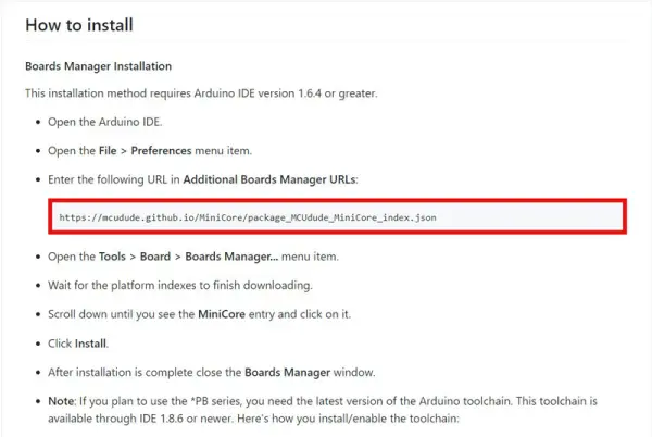
Launch the Arduino IDE and access the “Files” menu. Proceed to select “Preferences” from the dropdown and click on it. Once the preferences window opens, locate and click on “Additional Boards Manager URLs.” Paste the previously copied link into this field.
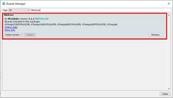
Navigate to the “Board Manager” by selecting “Tools” > “Board” > “Board Manager.” Allow time for the download to complete. Next, search for “MiniCore” and install it through the manager.
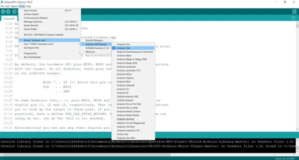
Navigate to the “Tools > Board” menu and select the MiniCore icon. From there, choose your desired microcontroller, such as the “Atmega8.”
At the bottom of the “Tools” menu, locate and click on “Burn Bootloader.” Wait for the process to complete; upon successful completion, the message “Done Burning Bootloader” will appear.
Once the bootloader has been successfully burned onto your microcontroller, you can proceed to program it using a USB to TTL adapter and the Arduino IDE. Let’s upload a simple code to the microcontroller to test its functionality.
Utilize the Arduino Board as a USB-to-TTL converter for programming the microcontroller through the RX and TX pins.
After setting up the circuit, reconnect the Arduino Board to the computer. In the “Tools” menu, ensure the following settings:
- Choose “Atmega8” under “Tools” > “Board.”
- Select the appropriate port where the Arduino Uno is connected under “Tools” > “Port.”
To verify the setup, upload a simple “Blink” code to the Atmega8 microcontroller and observe the results.
Below is the code snippet to be copied and pasted onto your microcontroller:
void setup() {
// initialize digital pin LED_BUILTIN as an output.
pinMode(8, OUTPUT);
}
// the loop function runs over and over again forever
void loop() {
digitalWrite(8, HIGH); // turn the LED on (HIGH is the voltage level)
delay(100); // wait for a second
digitalWrite(8, LOW); // turn the LED off by making the voltage LOW
delay(100); // wait for a second
}
By adhering to each step, the LED will initiate its blinking sequence. Feel free to modify the delay time and re-upload the code to confirm proper functionality.
- How do you make Arduino act as an ISP?
Upload the ArduinoISP sketch to the Arduino board; it provides firmware enabling the Arduino to function as an ISP. - What connections are needed between Arduino and AVR?
Connect SPI pins (MOSI, MISO, SCK), RESET, VCC, and GND between the Arduino and target AVR as per the circuit diagram. - How do you burn a bootloader onto an AVR using Arduino?
Select the correct board and port in Arduino IDE, choose Arduino as ISP in Programmer, then use Tools > Burn Bootloader. - Do you need additional board support for ATmega8?
Yes; add the MiniCore boards URL in Preferences, install MiniCore via Board Manager, then select ATmega8. - How do you install required libraries before uploading code?
Download and extract the specified libraries into the Arduino Libraries folder (Program Files(x86)/Arduino/Libraries). - Can Arduino be used as a USB-to-TTL converter to program the target MCU?
Yes; after burning the bootloader, the Arduino board can be used as a USB-to-TTL adapter via RX and TX pins to upload sketches. - What code is used to turn Arduino into an ISP?
Use the ArduinoISP sketch provided in the article (the long AVRISP sketch included in the Code section). - How do you test the AVR after burning the bootloader?
Upload a simple Blink sketch to the target MCU (example provided using pin 8) and observe the LED blinking. - Which Arduino IDE settings are required before burning?
Choose the correct board (e.g., Atmega8 via MiniCore), correct port, and select Arduino as ISP under Programmer. - What indicates successful bootloader burning?
The Arduino IDE displays Done Burning Bootloader when the process completes successfully.