Whether we care to admit it or not, motors can be found all over in our everyday lives; they just tend to be hidden. Motors are present in cars, printers, computers, washing machines, electric razors, and much more.
However, there are a number of people (which until recently included myself) that would be uncertain of how to make a motor run if they were handed one. So, let’s learn something today. Let’s learn how to use a stepper motor!
Step 1: Materials that I’m using
In order to demonstrate how to use the stepper motor (a hybrid stepper motor), there are a few things that I will end up using.
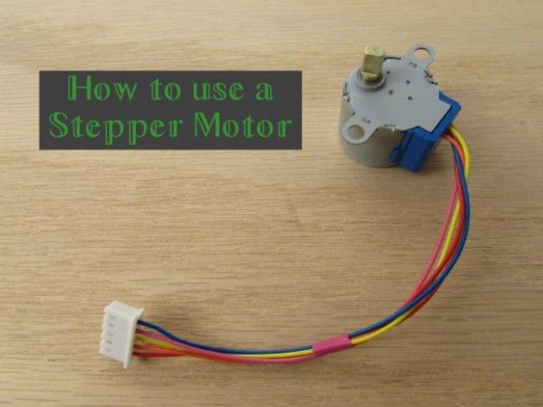
- The stepper motor itself, a 24BYJ48A
- A Darlington Transistor Array, ULN2803A
- a microcontroller, Digilent’s chipKIT uC32
- and a breadboard and breadboard wires
Both the stepper motor and the Darlington Transistor Array are available in the chipKIT Starter Kit.
Step 2: Stepper motor theory
Stepper motors are part of a class of motors known as brushless motors; these motors have a shaft but it does not physically touch anything in order to rotate. Rather, stepper motors work by utilizing electromagnets that are concentrically located around the shaft.
The idea behind electromagnets is that when a voltage of any kind is applied to a coil surrounding the piece of “soft” metal, that metal becomes magnetized until the current stops flowing through the coil. The central shaft rotates as the coils surrounding the electromagnets are brought to various voltage states. These voltage states create a magnetic polarity between the shaft and the electromagnet, causing the teeth of the shaft to line up with the teeth of the electromagnet. The motor can then be induced to spin by having the electromagnets appropriately change their polarity in a sequential fashion.
Step 3: Types of Stepper Motors
There are three main types of stepper motors that exist: variable inductance motors, permanent magnet motors, and hybrid motors. Variable inductance motors only use the generated magnetic field to make the central shaft rotate and line up with the energized electromagnets. Permanent magnet motors are similar except that the central shaft is polarized to have magnetic north and south pole which will appropriately rotate to whichever electromagnets are turned on. The difference between this and the variable inductance motor is that the permanent magnet motor’s central shaft does not have multiple “teeth”; just a north and south pole.
The hybrid motor, as you likely expect, is a combination of the two. Its magnetized central shaft has two sets of teeth for the two magnetic poles which then line up with the teeth along the electromagnets. Because of the double set of teeth on the central shaft, the hybrid motor has the smallest available step size and so is one of the more popular types of stepper motors. It is also the same type of motor that we will be primarily focusing on. You can learn more about the different types of stepper motors and how they are constructed here.
Step 4: Unipolar vs Bipolar stepper motors
There are two types of stepper motors: unipolar and bipolar stepper motors. On a fundamental level, these two types work exactly the same way; electromagnets are turned on in a sequential fashion, inducing the central motor shaft to spin.
The difference between the two types is the voltage levels. A unipolar stepper motor only operates with positive voltage, so the high and low voltages applied to the electromagnetic coils would be something like 5V and 0V. A bipolar stepper motor has two polarities, positive and negative, so its high and low voltages would be something like 2.5V and -2.5V.
Taking these electrical differences into account, the physical difference between these two styles is that the unipolar configuration requires an extra wire in the middle of each coil to allow current to flow through either to one end of the coil or the other. These two opposite directions produce the two polarities of the magnetic field, effectively mimicking the positive and negative voltage capabilities of the bipolar stepper motor.
Although both of these have a overall voltage range of 5V, the bipolar stepper motor will actually have more torque because current flows the entire coil, producing a stronger magnetic field to induce the shaft to rotate to the appropriate angle. On the other hand, unipolar stepper motors only utilize half of the coil length due to the extra wire in the middle of the coil, so less torque is available to magnetically hold the shaft in place.
Step 5: Stepper motor wires
Different stepper motors can have different amounts of wires, typically 4, 5, 6, or 8 wires. A 4-wire arrangement is only able to support bipolar stepper motors, since there is no central wire available.
5-wire and 6-wire arrangements can be used for both unipolar or bipolar stepper motors, depending if the center wire on each of the coils is used or not. The 5-wire configuration implies that the central wire on the two sets of coils are internally connected together.
An 8-wire arrangement, although relatively unused, is the most flexible out of all of the wire configurations as it can be run in a unipolar 5 or 6-wire arrangement, or bipolar mode with a parallel or series configuration.
This particular stepper motor that I am using has 5 wires, implying that it is to be run as a unipolar stepper motor. We learned that this 5th wire is to allow current on that particular coil to flow in two directions. But should we connect it to a 5V power line? Or to 0V ground line?
For more detail: How to use a Stepper Motor