This simple Arduino project can be placed in the doorway of a shop or other venue to count the number of people inside. Limiting the number of people inside a space can help to maintain social distancing. A demonstration of this project can be found here.
There is no soldering required in this project, since all components attach directly to the Arduino Uno.
This project uses two HC-SR04 Ultrasonic sensors to detect people; these are relatively inexpensive (~£2 each) and non-contact. These sensors communicate with the Arduino via the NewPing library by Tim Eckel.
Supplies:
- 1 x Arduino Uno
- 2 x HC-SR04 Ultrasonic sensor
- 2 x 560 Ohm resistor^
- 1 x 5V 5 mm Red LED
- 1 x 5V 5 mm Green LED
- Power supply*
- Correct USB cable for uploading sketch to Arduino board
^The value of the resistor will depend on the voltage drop across the LEDs you use. Anything from 150 Ohms to 750 Ohms will likely work.
* For regular use plug the Arduino into a 5V USB phone charger, USB power bank, or appropriate 6-12V DC power supply. For short term use (less than 1 day) a rechargeable 9V PP3 battery with snap connector to 2.1 mm DC barrel jack can be used
Step 1: Assembling the Circuit
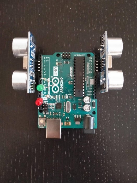
Please refer to the above image for assembly and also the bullet points below.
To attach the LED anode (positive leg) and resistor together I have used a technique called the Western Union (or Lineman) splice. This creates a mechanically strong electrical connection between the wires without solder. Be careful not to injure yourself on the sharp ends of the wires – using a pair of pliers and safety glasses is safest. If you prefer, you can connect the LED anode to a resistor leg with a female to female jump wire. Some HC-SR04 sensors come with straight pins, these should be attached to the Arduino with female to male jumper wires.
The components should then be attached as follows:
- The red LED cathode goes to GND
- The red LED’s resistor (spliced to the anode) goes to pin 12
- The green LED cathode goes to pin 11 (this will be set to GND later)
- The green LED’s resistor (spliced to the anode) goes to pin 9
- The first HC-SR04 connects: Vcc to pin A0, TRIG to A1, ECHO to A2, and GND to A3
- The second HC-SR04 connects: Vcc to pin 2, TRIG to 3, ECHO to 4, and GND to 5
That’s it; no soldering!
Step 2: Writing and Uploading the Code
The counter must calibrate to its surroundings in the setup() function, then detect and count people in the loop() function.
The calibration takes five readings form each sensor and averages them – this is the distance to the nearest wall. The threshold for detecting someone is then set as 75% of this value – this avoids the sensor being triggered or becoming uncalibrated if the product is knocked slightly. If the calibration returns silly values, like 0 cm or 300 cm, then the default threshold of 45 cm is used. Both LEDs are lit during this calibration phase to alert the user that it is ongoing. The product can be recalibrated at any time by pressing reset on the Arduino, this also resets the count to zero.
The loop takes a reading from each sensor. If this reading is less than the threshold then there is someone in that channel. If the previous reading from this sensor implied that no-one was there then the count increases for the in-sensor or decreases for the out-sensor. Comparing to the previous state of the sensor allows us to catch the rising-edge of the signal. The last thing to do is check the count against limit, if count >= limit light the red LED, else light the green LED.
You can copy this code or try coding from scratch:
/*
   This project was developed by the Design and Manufacturing Futures Lab at the University of Bristol as part of Project Clean Access
   More information about the lab and the project can be found here: <a href="https://dmf-lab.co.uk/project-clean-access/" rel="nofollow"> https://dmf-lab.co.uk/project-clean-access/</a>
   This code is for a counter to be placed in a shop entrance with separate entry and exit channels
   There are detailed instructions for this project on the Instructables website:

   The hardware required for this product:
   2 x HC-SR04 Ultrasonic sensor
   2 x 560 Ohm resistor
   1 x Red LED
   1 x Green LED
   1 x Arduino Uno
   Power supply
   Correct USB cable for uploading sketch to Arduino board

   Credit goes to Tim Eckel for developing the NewPing library and example sketches. More information here: <a href="https://www.arduino.cc/reference/en/libraries/newping/" rel="nofollow"> https://dmf-lab.co.uk/project-clean-access/
</a>
*/

#include <NewPing.h>
//Defining where the components are attached
#define TRIG_IN A1
#define TRIG_OUT 3
#define ECHO_IN A2
#define ECHO_OUT 4
#define LED_WAIT 12
#define LED_ENTER 9

#define iterations 5 //Number of readings in the calibration stage
#define MAX_DISTANCE 150 // Maximum distance (in cm) for the sensors to try to read.
#define DEFAULT_DISTANCE 45 // Default distance (in cm) is only used if calibration fails.
#define MIN_DISTANCE 15 // Minimum distance (in cm) for calibrated threshold.

float calibrate_in = 0, calibrate_out = 0; // The calibration in the setup() function will set these to appropriate values.
float distance_in, distance_out; // These are the distances (in cm) that each of the Ultrasonic sensors read.
int count = 0, limit = 5; //Occupancy limit should be set here: e.g. for maximum 8 people in the shop set 'limit = 8'.
bool prev_inblocked = false, prev_outblocked = false; //These booleans record whether the entry/exit was blocked on the previous reading of the sensor.

NewPing sonar[2] = {   // Sensor object array.
  NewPing(TRIG_IN, ECHO_IN, MAX_DISTANCE), // Each sensor's trigger pin, echo pin, and max distance to ping.
  NewPing(TRIG_OUT, ECHO_OUT, MAX_DISTANCE)
};

/*
   A quick note that the sonar.ping_cm() function returns 0 (cm) if the object is out of range / nothing is detected.
   We will include a test to remove these erroneous zero readings later.
*/

void setup() {
  Serial.begin(115200); // Open serial monitor at 115200 baud to see ping results.
  pinMode(2, OUTPUT); pinMode(5, OUTPUT); pinMode(A0, OUTPUT); pinMode(A3, OUTPUT); pinMode(11, OUTPUT);
  digitalWrite(2, HIGH); digitalWrite(5, LOW); digitalWrite(A0, HIGH); digitalWrite(A3, LOW); digitalWrite(11, LOW);
  pinMode(LED_WAIT, OUTPUT), pinMode(LED_ENTER, OUTPUT);
  digitalWrite(LED_WAIT, HIGH); digitalWrite(LED_ENTER, HIGH); //Both LEDs are lit to alert user to ongoing calibration.
  Serial.println("Calibrating...");
  delay(1500);
  for (int a = 0; a < iterations; a++) {
    delay(50);
    calibrate_in += sonar[0].ping_cm();
    delay(50);
    calibrate_out += sonar[1].ping_cm();
    delay(200);
  }
  calibrate_in = 0.75 * calibrate_in / iterations; //The threshold is set at 75% of the average of these readings. This should prevent the system counting people if it is knocked.
  calibrate_out = 0.75 * calibrate_out / iterations;

  if (calibrate_in > MAX_DISTANCE || calibrate_in < MIN_DISTANCE) { //If the calibration gave a reading outside of sensible bounds, then the default is used
    calibrate_in = DEFAULT_DISTANCE;
  }
  if (calibrate_out > MAX_DISTANCE || calibrate_out < MIN_DISTANCE) {
    calibrate_out = DEFAULT_DISTANCE;
  }

  Serial.print("Entry threshold set to: ");
  Serial.println(calibrate_in);
  Serial.print("Exit threshold set to: ");
  Serial.println(calibrate_out);
  digitalWrite(LED_WAIT, LOW); digitalWrite(LED_ENTER, LOW); //Both LEDs are off to alert user that calibration has finished.
  delay(1000);
}

void loop() {
  //  Serial.print("Count: ");
  //  Serial.println(count);
  distance_in = sonar[0].ping_cm();
  delay(40); // Wait 40 milliseconds between pings. 29ms should be the shortest delay between pings.
  distance_out = sonar[1].ping_cm();
  delay(40);
  if (distance_in < calibrate_in && distance_in > 0) { // If closer than wall/calibrated object (person is present) && throw out zero readings
    if (prev_inblocked == false) {
      count++; // Increase count by one
      Serial.print("Count: ");
      Serial.println(count);
    }
    prev_inblocked = true;
  } else {
    prev_inblocked = false;
  }
  if (distance_out < calibrate_out && distance_out > 0) {
    if (prev_outblocked == false) {
      count--; // Decrease count by one
      Serial.print("Count: ");
      Serial.println(count);
    }
    prev_outblocked = true;
  } else {
    prev_outblocked = false;
  }
//    //If there are fewer people in the shop than the limit, light is green, else it is red
  if (count < limit) {
    digitalWrite(LED_WAIT, LOW);
    digitalWrite(LED_ENTER, HIGH);
  } else {
    digitalWrite(LED_WAIT, HIGH);
    digitalWrite(LED_ENTER, LOW);
  }
}

<br>
Step 3: Setup, Calibration, and Use
I have found that the counter is most reliable when placed at hip/waist level, which is also a convenient angle for most people to see the LEDs. This can be achieved by placing the counter on a small table or on top of a barrier stand in the middle of the doorway.
You can see the counter setup and working here:
To calibrate the product simply power it on or to recalibrate press reset on the Arduino. Both LEDs will be lit to let you know it is calibrating. Once finished, these will both turn off then the green LED will light up. Calibration should be done when there are no customers in the shop. If there are, you can count these extra customers in by slowly moving your hand past the in-sensor – once per customer.
The default limit is five people. You can change that in the code, or you can effectively change this after setup. If you want to increase the limit to 8 people then slowly move your hand past the out-sensor three times. This will set the count to -3, from here 8 people can enter the shop before the LED turns red.
Occasionally, the counter will miss someone entering or leaving the shop. The ultrasound does not always reflect back to the receiver – this is most likely on soft materials like wool. The shopkeeper should check the count regularly (every hour) and adjust it if need be.
Step 4: Building a Case (optional)
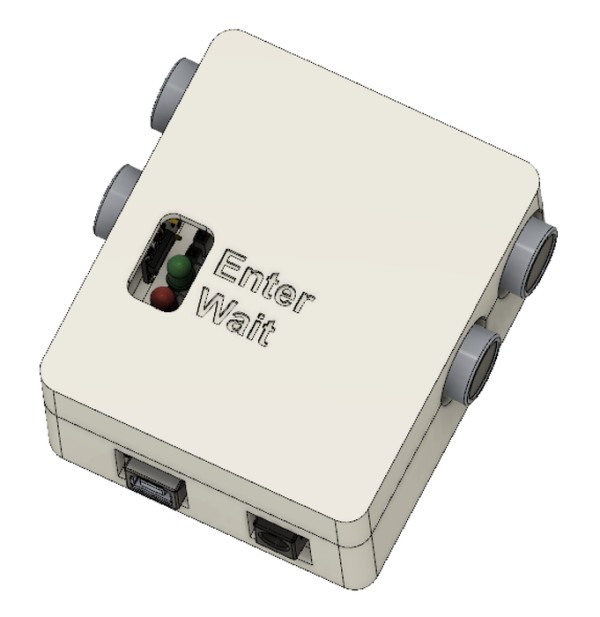
Because all of the components are secured into the Arduino, a case is not needed to hold the project together. However, a case will protect the electronics and make the product look more presentable.
I designed this case in Fusion 360 and it is intended to be 3D-printed in two parts (top and bottom). This case printed in about 5 hours on an Ender 3 in PLA. I added a little paint to the letters to make them stand out. The STEP and STL files are available for you to modify further or print.
Alternatively, a case could be designed for laser cutting with makercase. The designs from makercase can also be printed on a regular printer and used as templates for cutting other materials.
Step 5: Thanks

Thank you for reading this Instructable, I hope that you found it useful and have a go at making one of these yourself. You could even produce these for local shops to reopen safely as lockdowns are eased. The counter is most effective when accompanied by a poster. You can print off and display this one.
This Instructable was written for Project Clean Access at the Design and Manufacturing Futures Lab. Project Clean Access is kindly supported by the Royal Academy of Engineering and the University of Bristol.
P.S. I have also attached photos of some early prototypes to show how the final product looks neater without jumper wires and a breadboard.
Source: Ultrasonic Occupancy Counter (2-way)