About two years ago, I carried out a project involving a 2 wheel self-balancing robot from broken toy car. After upgrading it to new version, this broken toy car was left in my warehouse and I intended that someday I would make it operating again.
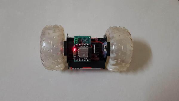
Today, I’m willing to share how to make a two wheels RC car which controlled by BEETLE-ESP32 microcontroller in the simple way.
This two wheels car can be fully functional remote controlled that allows the car to move forward, backward, turn left, turn right and some crazy movements by adjusting the discrepancy of 2 wheels speed, such as: perform 360 degree rapid rotation in vertical or horizontal direction….
Let’s getting started.
Step 1: THINGS WE NEED
Main components are as below:
- 1PCS X BEETLE ESP32 MICROCONTROLLER: https://www.dfrobot.com/product-1798.html
- 1PCS x L298N MOTOR DRIVER MODULE H-BRIDGE
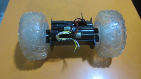
- 2PCS x WHEEL & DC GEAR-BOX REDUCER MOTOR: I reused 2 DC motors and 2 wheels with diameter ~100mm from broken toy car.
- 1PCS x DOUBLE SIDE DIY PROTOBOARD CIRCUIT 5x7CM.
- 2PCS X RECHARGEABLE BATTERY 18650 3.7V 4200mAh
- 1PCS X 2-PLACE 18650 BATTERY HOLDER WITH WIRES
- 1PCS X FEMALE 40PIN 2.54MM HEADER.
- 1PCS X MALE 40PIN 2.54MM HEADER.
- 1PCS X 2PIN 5.08MM PITCH SCREW TERMINAL BLOCK.
- 01METER X 8P RAINBOW RIBBON CABLE.
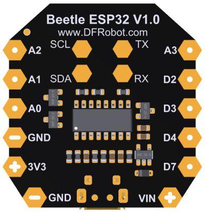
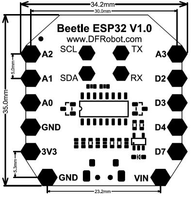
Step 2: BEETLE-ESP32 MICROCONTROLLER
With BEETLE-ESP32, Bluetooth and WIFI are integrated in microcontroller for supporting more applications. So I can easily build up a car which can be remotely controlled via WIFI or Bluetooth.
With dimension 35×34mm, Beetle-ESP32 is suitable for projects that require compact electronic components. It is equipped with 4 analog ports, 4 digital ports, UART and I2C interfaces.
For more detail, we can check at: https://www.dfrobot.com/product-1798.html
Step 3: CONNECTION DIAGRAM
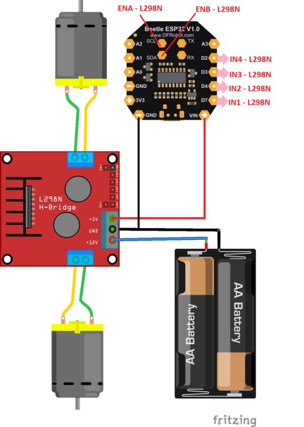
To control the direction and speed of 2 wheels car by L298N, we need 6 control signal outputs from BEETE-ESP32. The BEETLE-ESP32 has 4 digital ports and 4 analog ports but unfortunately, we cannot use 4 analog pins (A0 ~ A3) as outputs, only be used as inputs. With ESP32-WROOM-32, GPIOs 34 to 39 are GPIs – they’re input only pins.
- GPIO 34 – A2
- GPIO 35 – A3
- GPIO 36 – A0
- GPIO 39 – A1
So I had to use 2 pins of I2C interface (SCL and SDA) to control motor speed, they were connected to ENA and ENB pins of L298N.
Take note that L298N supply power to BEETLE-ESP32 at +5V & GND screw terminals.
For more detail, we can check their connection as table below:
Step 4: ASSEMBLY WORKS
SOLDERING HEADERS FOR BEETLE ESP32: The distance between the BEETLE ESP32 pins is 5 mm, so we can use the popular 2.5mm male/ female header and modify it a bit by this way: with every distance 5mm – 3 pins header, we remove a pin in the middle.
SOLDERING AN ADAPTER CONNECTING BEETLE-ESP32 AND L298N: Cutting double-sided proto-board into 2 equal parts. I used half of this proto-board to make the adapter shield which BEETLE-ESP32 can plug on its top and the L298N can plug at its bottom. The adapter shield was soldered following the schematic on previous step.
- Adapter shield – TOP: is connected to BEETLE-ESP32.
Adapter shield – BOTTOM: is connected to L298N at 6 pins female header.
BATTERY HOLDER: Glue battery holder to the car chassis. We need to test and ensure that battery holder and chassis including 2 DC motors can freely rotate around the car’s axle.
L298N INSTALLATION: Glue motor driver module H-bridge L298N and battery switch to the car chassis.
ADAPTER INSTALLATION: Connecting power supply wires to adapter shield. It supply +5VDC and GND to VIN of BEETLE-ESP32.
ASSEMBLY DONE: Plug adapter shield on the L298N. Due to car can be operated in high speed rotation so we need to arrange wires neatly, and fix all components firmly together by glue.
Step 5: PROGRAMMING
In the Arduino UNO/MEGA, we can use the analogWrite() function to generating PWM for control motor speed or LED applications. The ESP32 does not support the analogWrite() function but it does support a similar function, called ledcWrite(). We can refer to this funtion at below link:
https://github.com/espressif/arduino-esp32/blob/ma…
The ESP32 contains 16 independent “software PMW” channels and we can apply them to any 16 GPIOs output pins to generate PWM output with resolution up to to 16 bits.
In order to give a friendly use of analogWrite() function, we can use this tip:
#define analogWrite ledcWrite
The PWM function is declared and initiated as follow:
  // Config PWM functionalitites
  ledcSetup(pwmChannelA, freq, resolution);
  ledcSetup(pwmChannelB, freq, resolution);

  // Attach the PWM channel to the GPIOs to be controlled
  ledcAttachPin(ENA, pwmChannelA);
  ledcAttachPin(ENB, pwmChannelB);

  // Apply PWM at selected channels
  analogWrite(pwmChannelA, MotorLeft[2]);
  analogWrite(pwmChannelB, MotorRight[2]);
With BEETLE-ESP32, it can can be remotely controlled via WIFI or Bluetooth. In my case, I used WIFI with BLYNK app on the cellphone to control my car.
My two wheels RC car program is as below:
/* BEETLE ESP32 - TWO WHEELS CRAZY RC CAR
 * By TUENHIDIY
 */
/*
 * BEETLE-ESP32 PIN
 * D7  --> GPIO13
 * D4  --> GPIO27
 * D3  --> GPIO26
 * D2  --> GPIO25
 * A3  --> GPIO35
 * A2  --> GPIO34
 * A1  --> GPIO39
 * A0  --> GPIO36
 * SCL --> GPIO22
 * SDA --> GPIO21
 * TX  --> GPIO1
 * RX  --> GPIO3
 */

//#define BLYNK_PRINT Serial
#include <WiFi.h>
#include <WiFiClient.h>
#include <BlynkSimpleEsp32.h>
/*
 * Check detail at: https://github.com/espressif/arduino-esp32/blob/master/cores/esp32/esp32-hal-ledc.c
 * Turn ledcWrite() function into analogWrite() function as same as Arduino UNO or MEGA
 */
#define analogWrite ledcWrite

// Motor Left
const int IN1 = 13; // D7
const int IN2 = 27; // D4
const int ENA = 22; // SCL

// Motor Right
const int IN3 = 26; // D3
const int IN4 = 25; // D2
const int ENB = 21; // SDA

// Setting PWM properties
const int freq = 10000;
const int pwmChannelA = 0;
const int pwmChannelB = 1;
const int resolution = 8;

int INIT_SPEED = 150;
int LEFT_SPEED;
int RIGHT_SPEED;

// Motors properties
int MotorLeft[3] = {IN1,IN2, INIT_SPEED};
int MotorRight[3] = {IN3,IN4, INIT_SPEED};

// Auth Token in the Blynk App.
char auth[] = "";

// Your WiFi SSID and PASSWORD.
char ssid[] = "FPT-Telecom";
char pass[] = "12345678";

void setup()
{
  Blynk.begin(auth, ssid, pass);
  RC_Car_Init();
  // Serial Testing & Debugging
  //Serial.begin(115200);
  //Serial.print("Testing Crazy RC Car...");
}

//Intialize the motor
void RC_Car_Init()
{
  for(int i=0 ; i<2; i++)
  {
  pinMode(MotorLeft[i],OUTPUT);
  pinMode(MotorRight[i],OUTPUT);
  }
  pinMode(ENA, OUTPUT);
  pinMode(ENB, OUTPUT);

  // Config PWM functionalitites
  ledcSetup(pwmChannelA, freq, resolution);
  ledcSetup(pwmChannelB, freq, resolution);

  // Attach the PWM channel to the GPIOs to be controlled
  ledcAttachPin(ENA, pwmChannelA);
  ledcAttachPin(ENB, pwmChannelB);

  // Apply PWM at selected channels
  analogWrite(pwmChannelA, MotorLeft[2]);
  analogWrite(pwmChannelB, MotorRight[2]);
}

/*
  Two Wheels RC Car Driving Functions - L298N
    DIRECTION IN1 IN2 IN3 IN4
    Backward   0   1   0   1
    Forward    1   0   1   0
    Right      0   1   0   0
    Left       0   0   0   1
    Stop       0   0   0   0
*/

void RC_Car_Forward()
{
  // Serial.println("Moving Forward");
  analogWrite(pwmChannelA, MotorLeft[2]);
  analogWrite(pwmChannelB, MotorRight[2]);

  digitalWrite(MotorLeft[0],1);
  digitalWrite(MotorLeft[1],0);
  digitalWrite(MotorRight[0],1);
  digitalWrite(MotorRight[1],0);
}

void RC_Car_Backward()
{
  //Serial.println("Moving Backwards");
  analogWrite(pwmChannelA, MotorLeft[2]);
  analogWrite(pwmChannelB, MotorRight[2]);

  digitalWrite(MotorLeft[0],0);
  digitalWrite(MotorLeft[1],1);
  digitalWrite(MotorRight[0],0);
  digitalWrite(MotorRight[1],1);
}

void RC_Car_Left()
{
  //Serial.println("Turn Left");
  //analogWrite(pwmChannelA, 0);
  analogWrite(pwmChannelB, MotorRight[2]);

  digitalWrite(MotorLeft[0],0);
  digitalWrite(MotorLeft[1],0);
  digitalWrite(MotorRight[0],0);
  digitalWrite(MotorRight[1],1);
}
void RC_Car_Right()
{
  //Serial.println("Turn Right");
  analogWrite(pwmChannelA, MotorLeft[2]);
  //analogWrite(pwmChannelB, 0);

  digitalWrite(MotorLeft[0],0);
  digitalWrite(MotorLeft[1],1);
  digitalWrite(MotorRight[0],0);
  digitalWrite(MotorRight[1],0);
}

void RC_Car_Stop()
{
  //Serial.println("Motor Stopped");
  //analogWrite(pwmChannelA, 0);
  //analogWrite(pwmChannelB, 0);

  digitalWrite(MotorLeft[0],0);
  digitalWrite(MotorLeft[1],0);
  digitalWrite(MotorRight[0],0);
  digitalWrite(MotorRight[1],0);
}

BLYNK_WRITE(V1)
{
  int value_V1 = param.asInt(); // Get value as integer
  if(value_V1)
  {
    RC_Car_Forward();
  }
  else
  {
    RC_Car_Stop();
  }
}

BLYNK_WRITE(V2)
{
  int value_V2 = param.asInt(); // Get value as integer
  if(value_V2)
  {
    RC_Car_Right();
  }
  else
  {
    RC_Car_Stop();
  }
}

BLYNK_WRITE(V3)
{
  int value_V3 = param.asInt(); // Get value as integer
  if(value_V3)
  {
    RC_Car_Backward();
  }
  else
  {
    RC_Car_Stop();
  }
}

BLYNK_WRITE(V4)
{
  int value_V4 = param.asInt(); // Get value as integer
  if(value_V4)
  {
    RC_Car_Left();
  }
  else
  {
    RC_Car_Stop();
  }
}

BLYNK_WRITE(V5)
{
  int value_V5 = param.asInt(); // Get value as integer
  MotorLeft[2] = map(value_V5, 0, 100, 100, 255); // Mapping value from slider to PWM
}

BLYNK_WRITE(V6)
{
  int value_V6 = param.asInt(); // Get value as integer
  MotorRight[2] = map(value_V6, 0, 100, 100, 255); // Mapping value from slider to PWM
}

void loop()
{
 Blynk.run();
}
Source: TWO WHEELS CRAZY RC CAR