
Summary of Timelapse Panning controller for GoPro Cameras
This article details the construction of an Arduino-based Timelapse Panning Controller designed for GoPro cameras. The project integrates an Arduino Uno with a stepper motor and LCD keypad shield to automate camera panning. It covers circuit assembly, chassis fabrication using brackets and gears, and baseplate machining to ensure smooth motor operation.
Parts used in the Arduino Timelapse Panning Controller:
- Arduino Uno Board R3
- SainSmart LCD Keypad Shield
- 28BYJ-48 Stepper motor
- Female-Male Solderless Jumper Cables
- 7-pin male header pins
- 6x3x2 inch Radio Shack project Enclosure
- 12 tooth drive gear
- 36 tooth driven gear
- 3x3 plate from Hillman Hobby parts
- 1x3 bracket from Hillman Hobby parts
- 2x3 right angle bracket from Hillman Hobby Parts
- Short screws and nuts
- Long slender screws and nuts
- Nylon spacers
- Buttons
- 5mm drive shaft
This instructible will show you how I built (and you can also build) an Arduino Timelapse Panning controller for GoPro cameras. There are obviously some refinements that can be made to the design, but in general I am very happy with the results that I’ve captured with it. Check out the video below for a quick overview of the device.
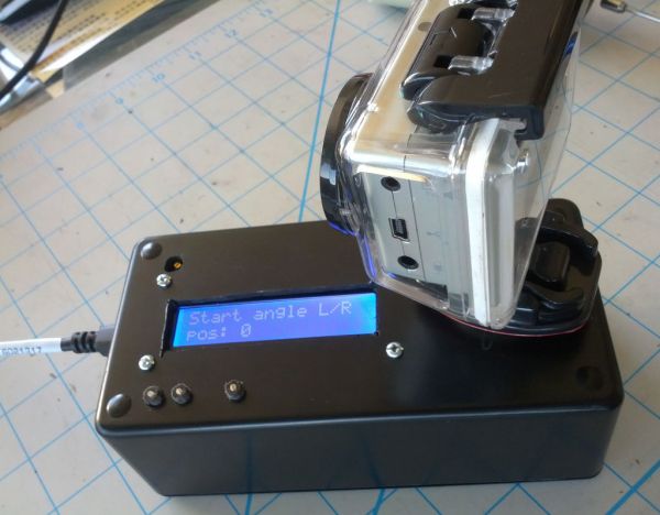
Step 1: Everything you need
What you will need:
1x Arduino Uno Board R3
1x SainSmart LCD Keypad Shield
1x 28BYJ-48 Stepper motor
5x Female-Male Solderless Jumper Cables
1x 7-pin male header pins
1x 6x3x2″ Radio Shack project Enclosure
1x 12 tooth drive gear
1x 36 tooth driven gear
2x 3×3 plate from Hillman Hobby parts
2x 1×3 bracket from Hillman Hobby parts
2x 2×3 right angle bracket from Hillman Hobby Parts
8x short screws and nuts
6x long, slender screws and nuts
4x nylon spacers
3x Buttons
1x 5mm drive shaft
Helpful haves:
Drill
Dremel or similar Rotary Tool
Picture hanging putty
2-part metal epoxy
Step 2: Circuit design
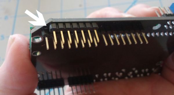
There’s nothing much to the circuit design. The Keypad Shield plugs straight onto the Arduino. You will need to solder a seven pin male header onto the keypad shield to get access to the pins which will power and control the motor.
Step 3: Building the chassis for he output shaft.
Begin by drilling out the center holes of the 1×3 brackets so they can accommodate the output shaft. Once they’re wide enough to accommodate the shaft without any binding, begin assembling the output shaft by mounting your driven gear and slide it throught he bottom bracket. I’ve added a nylon foot to the bottom of the shaft to keep it from binding on the baseplate.
Next, begin assembling the Chassis by attaching the top bracket to the two side panels. Notice that I arranged the bolts for the top bracket with the nuts facing outward – I’d had clearance issues with the driven gear. Then, attach the bottom bracket, the side panels and the L-brackets together to form the structure.
Step 4: Machining the baseplate
Use the completed chassis to mark out where you’ll need to drill the baseplate for mounting holes. Once you have the chassis mounted, line up the motor ensuring that the gears have a good interface. I find that placing a wad of picture putty under the motor helps with this. Then, drill the mounting holes for the motor and mount it into place using two of the longer, slender bolts.
For more detail: Timelapse Panning controller for GoPro Cameras
- What is the main purpose of this project?
The project builds an Arduino Timelapse Panning controller specifically for GoPro cameras. - How do you connect the keypad shield to the Arduino?
The Keypad Shield plugs straight onto the Arduino board. - Why is a seven pin male header soldered onto the shield?
It is soldered to get access to the pins that power and control the motor. - How do you prevent the output shaft from binding on the baseplate?
A nylon foot is added to the bottom of the shaft to keep it from binding. - What helps align the motor with the gears during assembly?
Placing a wad of picture putty under the motor helps with alignment. - How should the bolts be arranged on the top bracket?
The bolts are arranged with the nuts facing outward to avoid clearance issues with the driven gear. - Which tools are listed as helpful for this build?
A drill, Dremel or similar Rotary Tool, 2-part metal epoxy, and picture hanging putty are helpful.
