
Summary of Thermocouple Sensor 1.0 using arduino
This article describes a simple temperature measurement board using an AD595 chip to condition signals from Type K thermocouples. It details the circuit's interface, signal processing for linear temperature conversion, and accuracy considerations. The project includes options for DIY thermocouple fabrication, debugging via an alarm LED, and downloadable design files like Gerbers and Eagle source code.
Parts used in Thermocouple Sensor 1.0:
- AD595 chip
- Type K thermocouple
- +5 volt power supply
- Alarm LED
- PCB (Printed Circuit Board)
- Soldering toolkit
- Microcontroller or A/D converter (implied by analogRead function)
Overview
This is a simple board for measuring temperature. It uses an AD595 chip to make thermocouple measurements easy. The AD595 amplifies the thermocouple signal and conditions it for easy use. Thermocouples are great due to their linearity over a large range, and their high temperature capability (up to 1300C!)
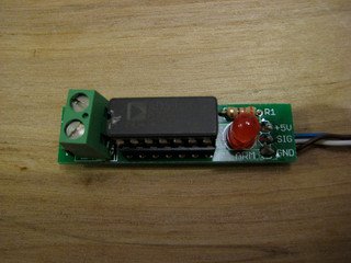
- You’ll need a soldering toolkit to do most of this.
- Read our Electronics Fabrication Guide if you’re new.
If you want to make your own thermocouples (a lot cheaper than buying them ready-made) then see this page.
Alternatives
There’s an alternative to this design here. A single layer version of the board is here.
Get It!
Full Kit
Raw Components
Files
You can download the electronics files from Sourceforge.
This file contains the following:
- GERBER files for getting it manufactured
- PDF files of the schematic, copper layers, and silkscreen
- Eagle source files for modification
- 3D rendered image as well as POVRay scene file
- exerciser code to test your board.
Interface
| Pin | Function |
| +5 | This is the pin to supply +5 volts on. |
| S | This is the signal pin. It will output a voltage between 0 and 5 volts that correlates with the temperature. |
| G | This is the ground pin. |
Signal Values
The nice thing about the AD595 is that the signal it generates is linear with temperature. This means that it is really easy to convert from an analog reading to a real temperature. Secondly, the AD595 outputs 10mV/C which is simple to work with. at 1V, the temperature is 100C, at 2V, the temperature is 200C, etc. With a reference voltage of 5V, the sensor can make readings up to 500C.
The way to read the temperature is easy. First you convert an analog reading to voltage, then you multiply by 100 to get the temperature in celsius:
Voltage = analogRead(X) * 5.0 / 1024.0; //Note that 5.0 is the A/D reference voltage. Celsius = Voltage * 100;
Or, to simplify:
Celsius = ( 5.0 * analogRead(X) * 100.0) / 1024.0;
More information in the AD595 datasheet.
Thanks to an article on uC Hobby for info on reading values from a very similar sensor.
Thermocouple
This circuit is designed to use the very common Type K thermocouple. There are many other types of thermocouples, and it may be possible to use them as well. You’ll get lots of mileage out of a Type K thermocouple though.
More about thermocouples on Wikipedia.
Alarm LED
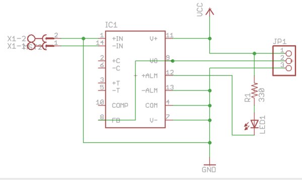
This LED lights up if there is no thermocouple connected or some other error (like the thermocouple failing, melting, etc). It’s a nice, easy way to help you debug things.
Accuracy
The circuit we have provided is very accurate, and will work well for our uses. We have made a few decisions to make the board simpler/easier to use that may slightly degrade its accuracy. However, its easy to build the board in a more accurate way:
- Use the AD595C (accuracy of +/- 1C) – more expensive than recommended AD595A (accuracy of +/- 3C).
- Solder the thermocouple directly to the board.
- Solder the AD595 directly to the board.
By using a more expensive chip and mounting the components directly to the board itself, you will be able to slightly increase the accuracy.
For more detail: Thermocouple Sensor 1.0
-
How does the AD595 process thermocouple signals?
The AD595 amplifies the thermocouple signal and conditions it to be linear with temperature, outputting 10mV per degree Celsius. -
What is the maximum temperature range of this sensor?
With a 5V reference voltage, the sensor can make readings up to 500C, though thermocouples themselves can handle up to 1300C. -
How do you calculate the temperature in Celsius from an analog reading?
Multiply the analog reading by 5.0, then by 100.0, and divide the result by 1024.0 to get the temperature in Celsius. -
Which type of thermocouple is designed for this circuit?
This circuit is specifically designed to use the very common Type K thermocouple. -
When does the Alarm LED light up?
The LED lights up if there is no thermocouple connected or if an error occurs, such as the thermocouple failing or melting. -
How can you increase the accuracy of the circuit?
You can increase accuracy by using the more expensive AD595C chip instead of the AD595A and soldering components directly to the board. -
What files are available for download regarding this project?
Downloadable files include GERBER files, PDF schematics, Eagle source files, 3D rendered images, and exerciser code. -
Can I make my own thermocouples for this project?
Yes, you can make your own thermocouples which are noted to be much cheaper than buying them ready-made.
