The Tier 2 Feeder is a big step up from the Tier 1. This version uses an ESP8266 wifi module to sync the arduino’s clock to control the feeding schedule and the tank’s lighting.
Step 1: What You Will Need:
- Everything in Tier 1 except the light timer
- ESP8266-01
- FTDI programmer (to program the ESP8266)
- Soldering iron
- 5V RGBW LED strip (SK6812 IP 65, daylight white, I used this one)
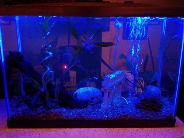
- The light strip needs to be waterproof, since water will evaporate from the tank and condense on the tank lid and lights themselves.
- 5V power supply (I used this one, the arduino CANNOT power all of the lights on its own.).
- Feel free to use any 5V power supply you want, just be sure it provides enough power to supply all of the lights.
- 3.3V voltage regulator
- The ESP8266 runs at 3.3V, this is why everything else is 5V, it’s easier to step 5 down to 3.3 than it is to step down 12 to 3.3
- Resistors (1kOhm x2, 2kOhm x2 (or 1kOhm x4), 10kOhm x1)
- Super glue
- Hot Glue
- 3D printed parts x8 (STL files provided)
- Wire strippers (I recommend these useful things)
- Breadboard (for protoyping things)
- Protoboard/Project board (for final assembly)
- Standard 3-prong computer power cable.
- (optional) Cell phone vibration motor (to agitate the hopper) (I used one of these)
- Install these arduino libraries:
- ESP8266WiFi.h
- WiFiUdp.h
- TimeLib.h
- Dusk2Dawn.h
- Adafruit_NeoPixel.h
- Patience.
Step 2: How It Works
The ESP8266 gets the Unix time from a NIST server and passes that to the arduino. The arduino then uses that time to determine local sunrise and sunset and sync its internal clock to determine how many minutes have elapsed since midnight. Using this elapsed time since midnight, the arduino sets the color of the lights and knows when to activate the feeder, which is the same mechanism as the Tier 1 freeder. The default settings in the arduino code I wrote have the lights set to a day/night cycle that can be controlled down to the second for smooth fades and are synced with your location’s sunrise and sunset. The arduino also resets itself once a day to re-sync itself with the NIST server and ensure there aren’t any timer overflows
Step 3: Programming the ESP8266
Okay, so the ESP8266 is a bastard to program.
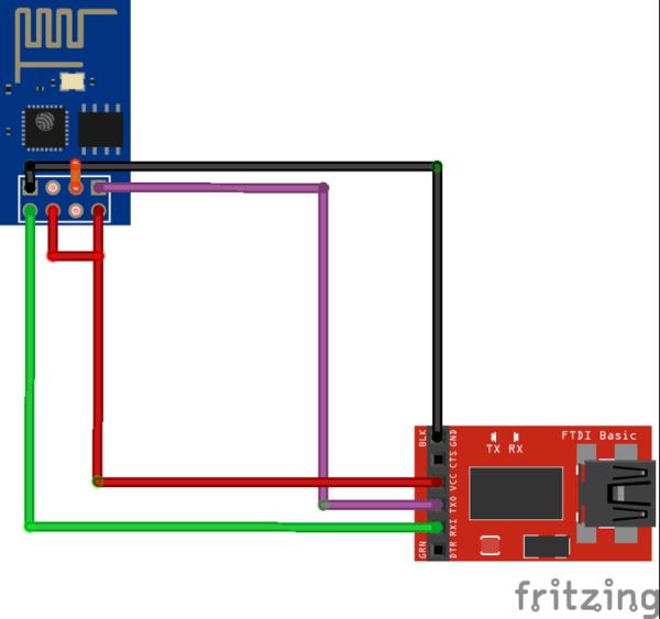
It is not breadboard friendly and if you have female jumper wires I recommend using those. If your ESP8266 came without any firmware installed like mine did, you’ll have to flash the firmware. Use the FTDI programmer to do this, there are plenty of instructions on how to do this elsewhere, but I provided a wiring diagram for convenience. MAKE SURE that the FTDI programmer is providing 3.3V! 5V will fry your ESP8266. In my diagram, the orange connected between GPI01 and GND should only be made when flashing the ESP8266’s firmware. GPI01 should remain unconnected when uploading actual arduino code to the module.
Next, you’ll have to upload the ESP8266’s actual code. Use the FTDI programmer this time along with the arduino IDE. You will also need to download and install all of the libraries used. The settings used to upload the code with arduino 1.8 are in the commented out portion in the beginning. BE SURE to update the code with your wifi network and password.
Step 4: Connect the ESP8266 to the Arduino
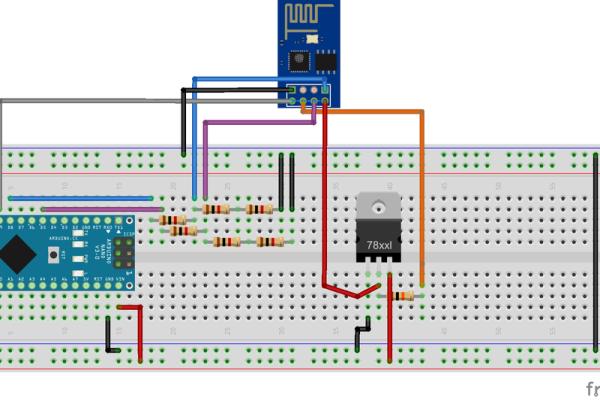
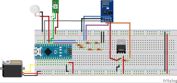
Once the code is uploaded, you can disconnect the FTDI programmer and connect the ESP8266 as shown in the diagram. The resistors are used as voltage dividers to make sure the arduino doesn’t pump 5V into the ESP8266’s communication and reset pins. Do this step on a bread board for debugging, we’ll put it on the proto-board later.
Once the ESP8266 is all plugged in, you should see a blue light flash when it’s connected to power, after a few seconds later it should get the Unix time from the internet and send that to the arduino, then it has an empty void loop() that it sits in until it’s reset, just like the Tier 1 feeder.
To make sure the ESP8266 is working, you will need to upload the code from the next step to the arduino and open the serial monitor.
Step 5: Uploading the Arduino Code and Troubleshooting
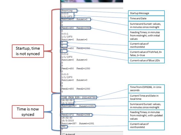
Now upload the code to the arduino nano, open up the serial monitor, you should see something like the example above. The arduino resets when you open the serial monitor, so the ESP8266 will get reset at the same time. the serial monitor will start counting the seconds from midnight on January 1 1970, until the ESP8266 sends it the current Unix time. When that happens you should see this:
It can take 3-15 seconds for this to work, so be patient. I’ve rarely seen it take longer than 10 seconds but give it 15 before you start troubleshooting.
If your ESP8266 isn’t sending the time to the arduino, try these steps:
· Make sure that everything is wired EXACTLY like it’s supposed to
· Double check that you put the correct wifi’s SSID and password into the ESP8266, if not you’ll have to hook it back up to the FTDI programmer to upload the correct information, then rewire it to the arduino. (a super long SSID or password may cause some issues, but my wifi network has over 20 characters in both fields so most home networks should be fine)
· Check your router’s admin page (if you can) for a connected device that only appears when the ESP8266 is on. To make sure it stays on while you check this(the arduino disables it) reconnect the wire leading to the ESP8266’s reset pin directly to 3.3V, keeping it HIGH will keep the ESP8266 on. Be sure to undo this after you check.
Step 6: Customizing the Arduino Code
Once your ESP8266 is connected and sending time to the arduino, the programmed arduino will simply count the time and display a few other bits of debugging information, like sunrise and sunset. We can customize some of these values in the arduino’s code, the rest are simply there so I could debug the entire system.
To better understand how the arduino calculates sunrise and sunset, read the documentation on the Dusk2Dawn Library. You will need to input your latitude and longitude (if you change the name of your location, make sure it is changed everywhere in the code!) Dusk2Dawn uses your gps coordinates (which you can find on google maps) and the local time, to determine when the sun rises and sets in minutes from midnight. The minfromMid variable is the current minute since midnight, and is compared against sunrise, sunset, the feeding times, and twilighttime to tell the arduino when to do what. Be sure to update your timezone as well, the default is EST.
Once your location is set, set twilight time to tell the arduino how long you want twilight to be. This controls how long the period between daytime and nighttime lasts, and is given in minutes. The default is 90 minutes, so the RGBW lights will fade from daytime to nighttime or the other way in that amount of time.
Next, set the feeding times you want. The actual feeding times are set in the getTime() method to keep the feedings synchronized with day/night. If you want your fish fed at the same time each day instead, comment out the relative settings and use the initial settings in the beginning of the code. Remember that these times are in minutes from midnight. Using initial, hard-coded feeding times could interfere with lighting if the feeding time lands during the fade between twilight and daylight (at sunrise and sunset). The default for the code is 15 minutes before and after sunset and sunrise, respectively. Additional feeding times can be added if you wish.
Next, set the time you want the arduino to reset. This ensures that none of the timing overflows and re-syncs the clock. I recommend making this happen mid-day, when you are away, since the reset process causes the lights to go full brightness. In the day this won’t be a problem for the fish, but at night or in the morning/evening, the flash of light could disturb your fish or ruin the look of the tank for a few seconds while you’re enjoying it.
Finally, check the number of LEDs in the strip you have, My strip has 60, but you should update this value in the setup code for however many LEDs you are using.
Step 7: The Lighting
Hook up your LED strip if you haven’t already.
Power (red) to 5V, ground (white) to ground, signal (green) to pin 6 (or whatever you set it to). Once the arduino is reset, the lights will be at full brightness until the ESP8266 sends the time to the arduino and it determines where it is in the lighting cycle. It’s best to set this up in the evening or night, since the light change will be more drastic. If the lights don’t change within 30 seconds, reset the arduino. My reset code should be working, but I am not a programmer by trade so there may still be a couple of bugs here or there. You can test the reset is working by setting the reset time to a minute after you re-upload the code and waiting (the reset second is randomized, so it may take 1-2 minutes to actually reset) You can do the same trick later on to make sure that the servo is working by changing the feeding time. Just be sure to change these times back before you leave it running.
The default lighting schedule is pretty simple:
At night, all the lights are off except blue, which is at it’s lowest setting (2/255). As the time approaches sunrise, the blue increases to it’s full intensity (255), which it reaches at the start of twilight. During twilight, red and green ramp up from off up to 255. At sunrise, red, blue, and green are all at 255, but daylight is white, so over the next 2 minutes red, blue, and green fade out and white fades in. Throughout the rest of the day white is at full intensity, until 2 minutes before sunset, when it fades out and is replaced by red, blue, and green again. At sunset, the lighting re-enters twilight, except this time red and green start at full intensity and fade out, leaving blue at full intensity when nighttime arrives. From here, the blue slowly fades back to it’s lowest value, which it reaches at midnight.
Other code exists at the end of the arduino sketch for other lighting modes, so feel free to play around with the math to get the lighting to fade differently or to change the colors during different periods of the day. Remember that the math is done in float format, but the color values have to be ints,so conversion is necessary between the two with any new lighting math you implement.
Step 8: Printing the Parts
If you haven’t printed the parts for this Tier yet, do so. The housing is about the same size as a medium-sized filter unit, and it took all night for me to print. Clean up the parts, insert the bulkhead divider, with the groove facing up and the rounded edge facing out. The servo is installed the same way as in Tier 1, and if you are replacing a Tier 1 system the hopper, lid, and feeding wheel are identical, so you won’t have to reprint them if they are working.
The .zip folder contains two sets of STL files, one for the original SM22 servo motor that I used and another for the far more common SG90 servo. Both contain the Fusion 360 files if you want/need to modify any of the parts. The SM22 STLs definitely fit together, since they are the ones I have used. I have not printed or tested the SG90 parts.
For materials, I recommend using a food-safe plastic. I used Raptor PLA from makergeeks, which comes in a ton of colors and is super strong after you anneal it for 10 minutes. That can be done by boiling the parts, which I recommend you do for just the wheel if it doesn’t quite fit since annealing will shrink the parts by about .3%.
I printed the housing on its side (with the top facing to the side and the open side facing up) This uses a lot less support material than other orientations. The hopper can be printed upside-down to avoid all support material on it. The hopper’s lid should also be printed upside down, however the big lid should be printed right-side-up.
There is also an ‘endstop’ piece to provide support to the bottom of the housing. After leaving the feeder in place for a couple weeks I noticed that it had started to sag and bend from the weight of the power supply, and that was affecting the hopper’s ability to feed food into the wheel. Just hot-glue 1-2 endstops to the bottom of the housing to keep everything level.
Source: The Ultimate DIY Automatic Fish Feeder: Tier 2