We are Master students in the field of Electro-mechanical engineering at The Brussels Faculty of Engineering, commonly known as “Bruface.” This project is a collaboration between two universities situated in the heart of Brussels: the Université Libre de Bruxelles (ULB) and the Vrije Universiteit Brussel (VUB).

As part of the program we had to make a real working mechatronic system for the course Mechatronics.
In our theoretical classes we were taught how to integrate various components to create actual applications. Following that, we received a presentation on the fundamentals of an Arduino microcontroller and managing a mechatronics system. The goal of the program was to learn how to create, manufacture, and code mechatronic systems.
All of this must be completed together as a team. Our team was made up of two Chinese students, two Belgian students, and one Cameroonian student, forming an international group.
To start, we would like to extend our gratitude for the assistance of Albert De Beir and Professor Bram Vanderborght.
As a team, we made the choice to address a socially important issue. As the aging population becomes a worldwide concern, the demand on caregivers and nurses increases significantly. As individuals age, they frequently need to consume additional medications and supplements. An automatic pill dispenser can help forgetful elderly individuals to manage their medication independently for a longer period of time. This will allow caregivers and nurses to dedicate additional time to patients who require more assistance.
Additionally, it would be quite useful for individuals who occasionally forget to take their medication due to memory lapses.
Therefore, the mechatronic system is required to provide a solution that prompts the user to take their medication and also dispenses the pills. We would also like the automatic pill dispenser to be easy to use so that people of all ages can utilize it.
Step 1: Materials
Casing:
- Mdf: 4 mm thickness for the inner case
- Mdf: 3 and 6 mm thickness for the outer case
Assembly
- Bolts and nuts (M2 and M3)
- Small ball bearing
Microcontroller:
- Arduino UNO [Order link]
Electronic parts
- Blank circuit board [Order link]
- Small Servo motor 9g [Order link]
- Small DC-motor 5V [Order link]
- Transistor: BC 237 (NPN bipolar transistor) [Order link]
- Diode 1N4001 (Peak Inverse Voltage of 50V) [Order link]
- Passive buzzer: Transducteur piezo
- LCD1602
- Resistors:
- 1 x 270 ohm
- 1 x 330 ohm
- 1 x 470 ohm
- 5 x 10k ohm
- Infrared emitter
- Infrared detector
Step 2: Inner Case

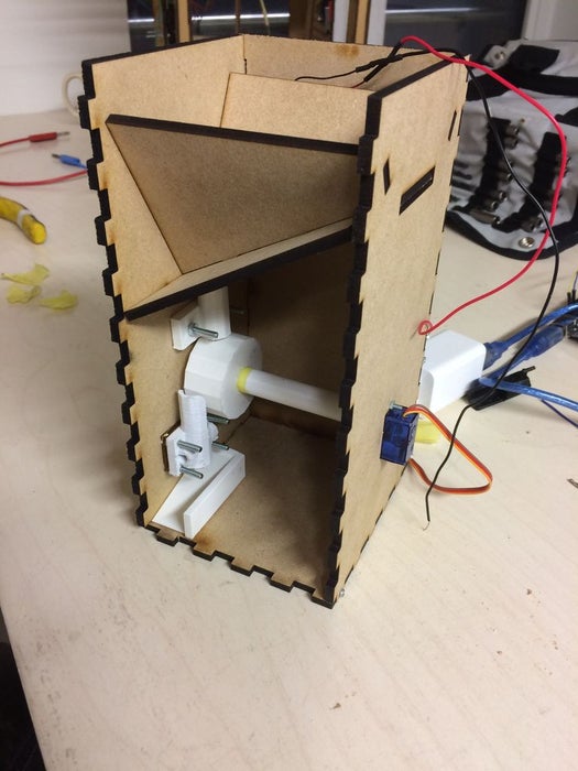
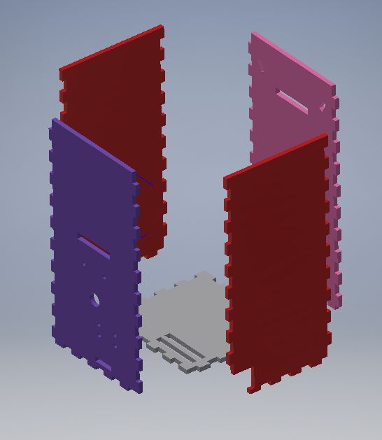
The inner case can be seen as the box that contains all inner mechanics and electronics. It consists of 5 plates of 4mm MDF that are laser cut into the right shapes. There is also an optional sixth plate one can add. This optional sixth piece has a square shape and can used as a lid. The 5 plates (the bottom and the four sides) are designed in a puzzle shape so that they fit perfectly within each other. Their assembly can be reinforced using screws. The planes already have the holes where the other parts should fit in or where the bolts should be placed.
Step 3: Inner Mechanism

THE DISPENSING MECHANISM
- Mechanism
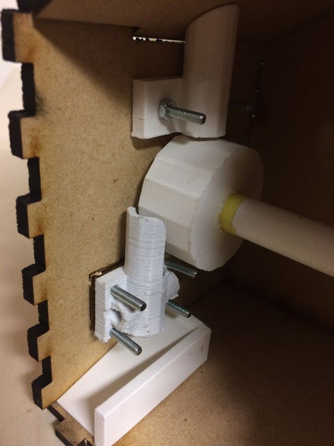
Our pill dispensing mechanism is as follows: the user puts the pills in the storage compartment in the top of the box. As the bottom plate of that compartment is slanted, the pills will automatically slide down into the first tube, where they stack up. Under this tube is a cylinder with a small hole in where just one pill fits perfectly in. This small hole is located right underneath the tube so that the pills stack up above it, while the first pill lays in the hole of the cylinder. When a pill has to be taken, the cylinder (with a pill in) rotates 120 degrees so that the pill in the cylinder falls down into a second cylinder. This second cylinder is where a sensor is located that detects if a pill has actually fallen down from the cylinder. This serves as feedback system. This tube has one side that sticks out higher than the other one. This is because this side prevents the pill from falling over the second tube, and thus helps guarantee that the pill will drop into the tube and will be detected by the sensor. Underneath this tube is located a small slide such that the dropping pill will slide trough the hole in the front of the inner box.
This whole mechanism needs several parts:
- Laser cut parts
- The bottom slanted plate of the storage compartment.
- The side slanted plates of the storage compartment
- 3D printed parts
- The upper tube
- The cylinder
- The axis
- The lower tube ( see the lower tube and sensor compartment)
- The slide
- Other parts
- Roll Bearing
All files of our parts that are needed to laser cut or 3D print can be found below.
- Different parts and their assembly
THE STORAGE COMPARTMENT PLATES
The storage compartment consists of three plates that laser cut. These plates can be assembled and connected to each other and the inner box because they have some holes and small pieces standing out. This is so that they all fit in each other like a puzzle! The holes and standing out pieces are already added to the CAD files one can use the laser cut it.
UPPER TUBE
The upper tube is only connected to one side of the inner box. It is connected with the help of a plate that is attached to it (it is included in the CAD drawing for the 3D printing).
CYLINDER & ROLL BEARING
The cylinder is connected to 2 sides of the box. On one side, it is connected to the servo motor that induces the rotating motion when a pill has to drop. On the other side, it
THE LOWER TUBE AND SENSOR COMPARTMENT
Sensing is an important action when it comes to pill dispensing. We must be able to get a confirmation that an allocated pill has been taken by patient at an appropriate time. To get this functionality, it important to considered the various design steps.
- Choosing the correct detecting components:
From on set when the project was validated, we had to search for and appropriate component that will confirm the passage of a pill from the box. Knowing sensors can be of use for this action, the main challenge was to know the type that will be compatible with the design. The first component we found was a photointeruptor composing of an IR emitter and IR phototransistor diode. The 25/64’’ slot PCB HS 810 photointeruptor was a solution due to its compatibility making us to avoid the possible problem of angle configuration. We decided not to use this due to it geometry, it will be difficult to incorporate with the nozzle. From some related project we saw that it’s possible to use an IR emitter with an IR detector with fewer other components as a sensor. These IR components could be found in various shapes.
- 3D printing of the pill nozzle that holes the sensor
Being able to sort out the main component to be used as sensor, it was then time to check on how they will be place on the nozzle. The nozzle has an inner diameter of 10mm for the free passage of pill from the rotating cylinder. By the data sheet of the sensing elements, we realized that introducing holes around the nozzle surface corresponding to the dimension of the component will be an added advantage. Should these holes be place at any point along the surface? no because to achieve maximum detection the angularity needs to be evaluated. We printed a prototype based on the specifications above and did check for detectability.
- Evaluating the possible beam angle and detection angle
From the data sheet of the sensor components, the beam and detection angle are 20 degrees, this means that both the emitting light and detector have a wide span of 20 degrees. Though these are manufactures specification, it’s still important to test and confirm. This was done by simply playing with the components introducing a DC source alongside an LED. The conclusion reached was to place them opposite to each other.
- Assembly
The 3D print design of the tube has a plate connected to it with 4 holes. These holes are used to connect the tube to the inner case by using bolts.
Step 4: Electronics Inner Mechanism

- Dispensing mechanism:
The dispensing mechanism is achieved by using a small servomotor for the rotation of the big cylinder.
The drive pin for the ‘Reely Micro-servo 9g’ servo motor is connected directly to the microcontroller. The microcontroller Arduino Uno easily can be used for the control of the servo motor. This because of the existence of the built-in library for servo motor actions. For example with the ‘write’-command, the desired angles of 0° and 120°can be reached. (This is done in the project-code with ‘servo.write(0)’ and ‘servo.write(120)’).
- Vibrator:
Small brushless DC motor with unbalance
This unbalance is achieved with piece of plastic which connects the motor axis with small bolt and nut.
The motor is driven by a small transistor, this is done because the digital pin can not deliver higher currents than 40.0 mA. By providing the current from the Vin pin of the Arduino Uno microcontroller, one can reach currents up to 200.0 mA. This is enough to power the small DC-motor.
When the motor powering is abruptly stopped, you get a current peak due to the self inductance of the motor. So a diode is placed over the motor connections in order to prevent this back flows of the current which can damage the microcontroller.
- sensor system:
Using an infrared emitter diode(LTE-4208) and an infrared detector diode (LTR-320 8) connected to Arduino Uno microcontroller to confirm the passage of a pill. Once a pill fall down, it would shade the light of infrared emitter diode in a short time. Using an analogpin of the arduino we would get this information.
for detection:
analogRead(A0)
Step 5: Outer Case

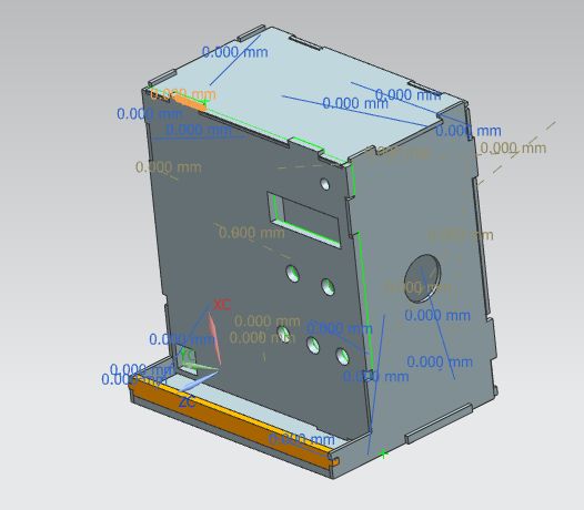
- Size:200 x 110 x 210 mm
- Material:medium density fiberboard
- Thickness of sheet: 3 mm 6 mm
- Processing method:laser cutting
For the outer case, we used different kinds of thicknesses because of errors of the laser cutting. We choose the 3 mm and 6 mm to make sure all sheets can be combined tightly.
For size, considering the space for the inner case and electronic devices, the width and height of the outer case is litter bigger than the inner one. The length is much longer to allow space for the electronic devices. Moreover, in order to make sure the pills can drop out of the box easily, we kept the inner and outer case very close.
Source: The Automatic Pill Dispenser
