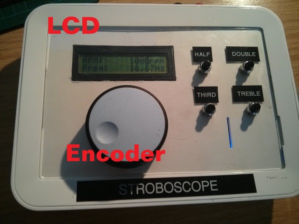
Summary of Stroboscope
This article details a custom stroboscope project built to measure motor RPM, chosen over simpler beam-break methods for its generic applicability. The device uses an Arduino Nano to generate rectangular waves for a light source, featuring an LCD display and rotary encoder for user control. It allows setting flash rates via frequency or RPM, adjusting duty cycles independently, and includes buttons for rapid rate adjustments (halving/doubling) to verify rotation multiples.
Parts used in the Stroboscope:
- Arduino Uno (for prototyping)
- Arduino Nano (for final board)
- Rectangular wave generator
- Light source
- 2×16 LCD display
- Rotary encoder with button
- Control buttons for halving/doubling/thirding/trebling rates
- Beefy output stage for switching LED sets
Introduction
For a Nottingham Hackspace project, I was asked if I could measure the RPM of a motor. “Sure!”, I said.
What was really needed was quickly bodging together a beam-break circuit and connecting it to an oscilloscope. This would have taken a couple of hours at the most. But like a proper software engineer, I decided to make the “generic” solution to the problem, which took ages.
There are actually two ways to measure RPM electronically
- Using a beam-break or reflective sensor and a counter, which provides a direct measurement.
- Using a strobe light and adjusting the frequency until the rotating object appears stationary.
I went with the second option – building a stroboscope.
System Design
At its heart, a stroboscope is just a rectangular wave generator hooked up to a light source. I wanted a few extra features to make it nice to use:
- Ability to set flash rate by either frequency or RPM
- Set duty cycle of output without affecting flash rate
- LCD display
- 2×16 for displaying RPM, frequency and duty (one per line, so one will be hidden at any time)
- Rotary encoder (with button) for main interface
- When button is not pressed, knob will increase/decrease the value of the selected digit
- When button is pressed, rotating knob will scroll through display digits
- Buttons for quickly halfing/doubling thirding/trebling the flash rate
- This is useful for checking that you haven’t hit on a multiple of the rotation rate
- Nice beefy output stage for switch big sets of LEDs
The system was prototyped on an Arduino Uno, and then a Nano was used for the actual board. The basic hardware diagram looks like this:
For more detail: Stroboscope
- What are the two ways to measure RPM electronically?
The two ways are using a beam-break or reflective sensor with a counter, or using a strobe light and adjusting frequency until the object appears stationary. - Why did the author choose to build a stroboscope instead of a beam-break circuit?
The author chose the stroboscope to create a generic solution rather than quickly bodging together a specific beam-break circuit. - How can users set the flash rate on this device?
Users can set the flash rate by either specifying the frequency or the RPM directly. - What is the function of the rotary encoder button?
When pressed, rotating the knob scrolls through the display digits; when not pressed, it increases or decreases the value of the selected digit. - What do the dedicated buttons do on the interface?
The buttons allow users to quickly half, double, third, or treble the flash rate to check for multiples of the rotation rate. - Can the duty cycle be adjusted without affecting the flash rate?
Yes, the system design allows setting the duty cycle of the output without affecting the flash rate. - What hardware was used for the final version of the board?
The actual board used an Arduino Nano after being prototyped on an Arduino Uno. - What is the purpose of the beefy output stage?
The output stage is designed to switch big sets of LEDs.