Purpose of the Project: Creating a rock-paper-scissors game with a servo motor module, joystick module, module with lcd (I2c) and distance sensor using the Pinoo control card.
Duration: 2 lessons
Age Group: 7 years and older
Pinoo Set: Maker Set, Full Set.
Benefits:
• Learns to code Pinoo control card.
• Learns to code the distance sensor.
• Learns to code the Servo Motor module.
• Learns to code the joystick module.
• Learns to code the LCD module.
• Improves the skill of setting up algorithms.
• Improves coding skill.
• Design skill develops.
• Designs and plays his own game
Supplies
Materials to be Used: Mblock 3 program, Pinoo control card, distance sensor, 3 servo motor modules, connection cables, joystick module, module with LCD (I2C)
Materials Required for Design: Dekota, colored cardboard, cardboard in different colors, eva, silicone gun and silicone, pencil, screwdriver, scissors, knife, ruler.
Step 1: Project Preparation
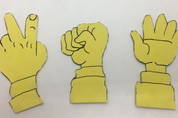
- We draw the hand shapes of the stone, paper, scissors game on the colored cardboard and cut them with the help of scissors.
- Using a ruler and pencil, we draw two 36x30cm rectangles on the deco. We cut rectangles with the help of a knife.
- Using a ruler and pencil, we draw two 10x36cm rectangles on the decorate and cut them with the help of a curved knife.
- Using a ruler and pencil, we draw two rectangles of 10x30cm on the decorator and cut them with the help of a curved knife.
- With the help of a silicon gun, we glue the pieces we cut from the decota as shown in the figure and form a box.
- Note: We do not paste the upper part of the box, we will paste it after our codes are finished.
- We drill rectangular holes as far as the Pinoo control card can pass, to coincide with the back of the box we created.
- We take the part we cut for the top of the box. By placing the sensors and modules we will use on it, we determine their positions.
- Note: We arrange the hands so that they do not hit each other and the sensors.
- We draw the eyes of the sensor on the section we have set to place the distance sensor and cut it with the help of a knife.
Step 2: Circuit

- With the help of a silicon gun, we mount the servo motor modules and the distance sensor to the holes we drilled as shown in the figure.
- We install the propellers of the servo motor modules horizontally, with their ends facing left and right. We fix the screws using a screwdriver to be strong.
- NOTE: Before fixing the propellers of the servo motor modules, we definitely encode them to 180 degrees!
- We assemble the stone, paper and scissors drawings we made at the very beginning of the design to the propellers of the servo motor modules with the help of a silicon gun as shown in the figure.
- We mount the joystick module to the square hole we drilled with the help of a silicone gun.
- We connect the LCD (I2C) module to the converter so that the GND parts correspond to each other. Then we mount it to the rectangular hole we opened with the help of a silicone gun.
- We make connections with the modules of the servo motors in a way that corresponds to the “Brown cable-GND, Red cable-5V, Orange cable-D0”.
- We connect the modules and the sensor to the Pinoo control card with the help of a connection cable. We connect the LCD (I2C) module to the red / white input number 10.We connect the joystick module to the red / yellow input number 9.
- We connect the distance sensor to the purple / green input number 5. When we reverse the decode, we connect the servo motor modules to the purple inputs 2,3,4 respectively, starting from the left. (scissors-2nd entrance, paper-3rd entrance, stone-4th entrance)
- We draw the hand shapes of the game of stone, paper, scissors again on colored cardboard and cut them with the help of scissors.
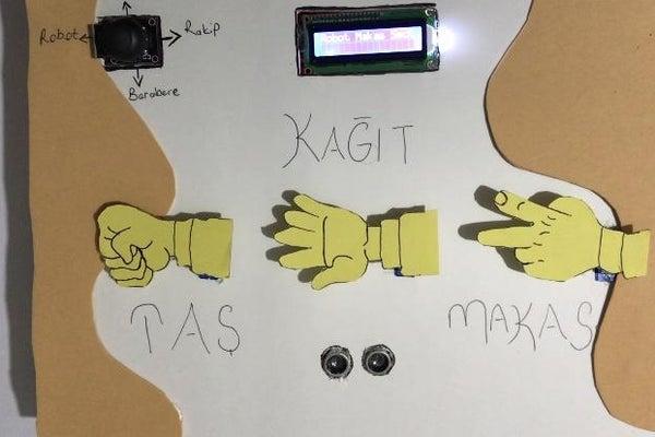
- We assemble the upper part of our box with the help of a silicon gun as shown in the figure. Then we decorate it with evas and hand shapes as we want.
- NOTE: It will be healthier to assemble the upper part of the box after the coding is completed.
Step 3: Connection

- We have completed the connections and the design, now we move on to the coding part. We will use Mblock-3 application for this.
- We connect our Pinoo control card to the computer with the help of a connection cable and enter the Mblock3 application. Then we introduce our Pinoo control card to the computer. For this, we first click on the serial port option from the Connect tab. Then we choose COM3. (The number may differ depending on the computer and the port.)
- After making the serial port connection, we select the card to be used from the Cards tab. We are working with Arduino Nano model.
- In order to add the Pinoo extension to our computer, we click on the Manage Extensions option from the Extensions tab. In the window that opens, we type “Pinoo” into the search engine and simply say download to the result. It was installed on our computer.
- We come to the Extensions tab again and click on the Pinoo option. We will write our codes with the Pinoo extension.
- Come to the ‘Connect Again’ tab and click on the ‘Firmware Update’ option. After saying that the installation is finished, we press the ‘Close’ button.
Step 4: Code (Part1)

- In the coding part; To start the application, we get the code when clicking the Green Flag from the Events menu.
- From the Robots menu, we get the code related to the servo motor modules and change the pin inputs one by one and set them all to 180 degrees.
- When the Green flag is clicked from the vents menu, we get the command. We get help from the dummy to learn the value read by the distance sensor. For this, we get the “say hello” command from the View tab. Instead of the word ‘Hello’, we get the code block for the distance sensor from the r,Robots tab. We change the pin input to Pinoo5 that we connect.
- Since we want it to do the reading process continuously, not once, we take all our codes into the continuous repeat block from the Control tab.
- We click on the green flag and zoom in and out of the distance sensor. Here, when we bring our hand closer, we will take as a reference that it reads less than 10.
- We need to define a variable in order to see the values that the joystick module takes in x and y positions. For this, we come to the Data & Block menu and say create a variable.
- We write the variable name on the screen that appears.
- We define separate variables for X and Y positions.
- When the space key is pressed from the Events, we get the command. Since we will read the values continuously, we get the continuous repeat command from the Control menu. We take the codes “let x be 0, y get 0” from the Data & Block menu and put them into the ‘continuous repeat’ command.
- We synchronize the positions of the joystick module with the positions we have defined
- We press the spacebar and observe the values of the joystick module. When the joystick module is not moved, it takes around 500 values. When we pull it up, the y position approaches 0 and when we pull it down, it approaches 1022. When we pull it to the right, the x position approaches 1022 and when we pull it to the left it approaches 0.
Step 5: Code(Part2)

- We need the library to be able to use the LCD (I2C) module. (You can find the library in the files.) We move the library of the LCD module to libraries by following the steps of program files- Mblock- Arduino-libraries from our computer.
- https://drive.google.com/drive/folders/1oDHzYkPM2I…
- We check if the LCD module is working or not. We cannot use the LCD module with the codes in events. In order to use it, we need to load into the Arduino board.
- For this, we get the Pinoo program code from the Robots tab. Then we define the model of our LCD module. (Usually the ones used are 0x27 and 0x3F. You must choose your own model.) Our LCD module consists of 2 rows and 16 columns. We choose from which row and from which column we will start printing our article. Then we write ‘’Welcome to the Game’’ …
- Right click on the code and click the ‘’Upload to Arduino’’ option. (We work with Arduino as a card.)
- In the window that opens, we click the ‘’Upload to Arduino’’ button again.
- We are disconnected because we loaded into the card. To write code, we choose Connect-Serial port-Com again and update the firmware.We define two variables called robot and opponent to keep track of the scores of the game. And we say that the scores are 0 when the game starts (that is, when the green flag is clicked) just below the green flag that we made the servo motors 180 degrees.
- We want the game to begin when we pull the joystick module up and the distance sensor is smaller than 10 (when we bring our hand closer). For this, we use the conditional commands, if any. We say if the Y axis is less than 300 because when we pull it up, the value is approaching 0.
- When we pull the joystick module up and the distance is less than 10, we say the servo motor modules should move up and down at 135 and 180 degrees three times.
- If the joystick module is not pulled up and the distance is greater than 10, we say that the servo motor modules remain at 180 degrees.
- If the joystick module is above and the distance is less than 10, we add to the codes. If the conditions are met, we call the number between 1 and 3. (There are 3 possibilities for rock, paper, scissors) And if the number it holds is equal to 1, we say clean the LCD screen. (If not cleared, the articles will overlap.)
- Then we say that the servo motor module (ie the stone) at the 2nd entrance should lift up 90 degrees. And we say the others should stay at 180 degrees. Then we print on the LCD module, we chose a Robot stone.
- With the same logic, we also code the cases where the number is equal to 2 and 3.
- If the sign selected by the robot is the same as the sign we made, we want both sides not to gain points. We will define it as a draw when we pull down the joystick module. If the joystick module is pulled down, the LCD module display will be cleared. We print the robot’s score on the 1st line and the opponent’s score on the 2nd line. And we bring the hands back to their former position.
- We want the opponent to win 1 point if our sign beats the mark made by the robot. For this, when we pull the joystick module to the right, we determine the opponent as the winner. And if the opponent’s score is equal to 3, we say victory should be written on the screen. And we end the game by resetting the scores.
- We click on the Green Flag button and check our project. (LCD modules will work after loading into the board.) If there is no problem in the operation of our project, we need to load the codes we have written into our card in order to run our project with a power source independent of the computer.
- For this, we delete the code when the green flag we used at the beginning is clicked. And we combine it with the codes we use to control the LCD module.
- Then we repeat the process of loading into the card.
- If there is no problem, we disconnect our power cable from the computer. We power our Pinoo control board with the help of a 9v battery and a battery cap. We also turn the on / off button right next to the battery input to the ON position.
Step 6: Working Status of the Project
- When the joystick module is not pulled up and the value measured by the distance sensor is not less than 10, the servo motor modules will not move and will stop at 180 degrees.
- When the joystick module is pulled up and we put our hand in front of the distance sensor, the servo motor modules will move up and down 3 times and then make a random movement.
Source: Stone-Paper-Scissors Game With Pinoo