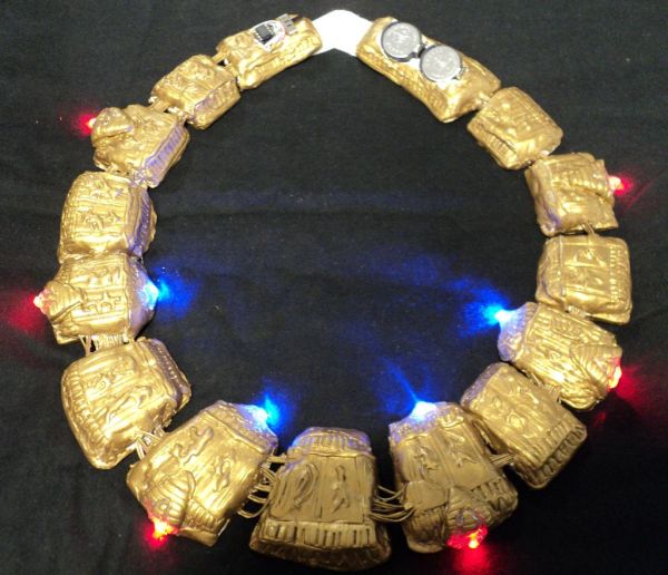
Ever need to have a Stargate handy? You can wear one around your neck and have it at the ready. Ears starting to bleed from the volume of the music at the club or that Euro-chic clothing retailer outlet? Activate the Stargate to jump to another world. Light sequence needs to be just right. Don’t know where I’m going to but I’m on my way.
 Make this piece of costume, uh, costume jewelry. Plated in fashionable fine gold naquadah, it is quite refined in looks and operation. The underlying technology of the Ancients may be mysterious but read on to build one yourself. But wait, there’s more, Stargate Gong available too.
Step 1: Need to make a collect call…
This project is about merging new world technology with old world crafting.
The Stargate Necklace is fashioned from air-hardening clay and painted in metallic gold acrylic.
The working lights or LEDs are controlled with a standalone microprocessor Attiny85.
It is powered by two CR2032 coin cells giving us about 6 volts power.
———————————————————————————————————————–
The heart of the electronics in this necklace is the Attiny85. You need an AVR programmer to program the chip.
You need some thin wire to use to wire the LEDs and batteries to the processor.
I threw in an on/off slide switch.
I used 130 ohm resistors to pair with each LED.
Once the wiring harness is built with all the electronics, it is encased with air-hardening clay to form the Stargate.
You can paint it the archeological dig weathered concrete gray or I chose the fancier metallic gold color.
Step 2: Program the Attiny85
Since a necklace has limited space to embed in a circuit board, using a full size Arduino or even a wearable FLORA would have not worked as a choice. We can use a stand-alone microprocessor chip like an Attiny85 to control our blinking lights. There are other Attiny chips out there with more or less pins but I had some Attiny85s on hand to experiment.
I had planned out where I wanted LEDs in the necklace. Based on the 5 pins available on the Attiny85 (5 input/outout, reset, GND, v+) , I could pair up LEDs for each pin to give me 10 LED lights to work with. You really have to account for the max output or current draw on each pin and what your LEDs draw. From experience, I knew I could live dangerously by using 2 paralled wired LEDs with resistors on each pin of the chip. With all LEDs full on, I don’t think I would burn out the chip…completely Doing a matrix of LEDs is more complicated and I wanted just to do something simple. Look up “charlieplexing” to see how to light up more LEDs with a limited number of pins on the chip.
Lighting up the LEDs is the basic digital write to turn on the LED.
To get it to light up in a pattern, you have to program the Attiny chip. If you do not have an AVR programming device, you can write the code to the Attiny by using an Arduino board hooked up to your PC as the programming device.
And so this is my adventure in programming an Attiny85….
There are a lot of ibles already on programming an Attiny. Lots of people have already done it, so can I.
I am not going to repeat or include any of the details since they are repeated in all those ibles.
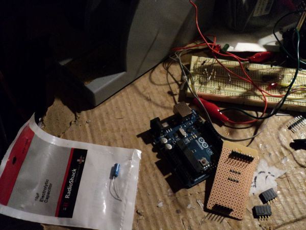
Load an ISP sketch so the Arduino will act as an AVR programmer.
Short out the reset pin and 5v+ with a capacitor on the Arduino so it does not keep on autoresetting itself during the process.
Wire certain pins from the Attiny to the Arduino to establish communication and power.
Burn a bootloader to the Attiny to set the speed it should run at.
Don’t forget to change the board setting in the menu that you are burning an Attiny85 at 8mhz clock.
Upload your sketch to the Attiny through the regular Arduino IDE.
It is so simple to set up.
———————————————————————————————————
I had my sketch all worked out to light my LEDs in a pattern on the Arduino.
I just had to change the pin assigments to match up with the ones on the Attiny.
Note that some commands are not supported on the Attiny that are available on the Arduino. I was just doing some basic stuff.
I built a little AVR programming shield because wiring up the chip and the Arduino is such a chore even with a breadboard. If you use header pins to plug into the Arduino, note it is the weird spacing and placement of the female header rows on the Arduino board that make it seem your pins are out of place and you will need to align everything by eye before you plug it in.
To make a long story short; I was ready to program my first Attiny. With the ISP loaded on the Arduino, I plugged in my shield with the chip. A nice pulsating glow from the heartbeat LED, actually it was really too bright so I put a piece of tape over it. Hit upload. I got every error that all those ibles told you to ignore. I set up the Attiny to run stand-alone. Nothing.
(Over a span of an hour or more…) Check recheck shield wiring, reprogram ISP, install every version of Arduino IDE 022 through 1.05, wire directly without the shield, use resistors to short the reset on my UNO, research other errors or where the uploader was hanging… Put is all away to try again the next day. Really ready to give up.
———————————————————————————————————
So next day… After reading all the support forums on why the chip burning was not going too well, I decided to pop in a second chip. I had gotten a set of 5 from ebay so I was also thinking these were bum chips. I even looked up Attiny85v and the ones marked -10p or -20p which is what I had. This new chip was giving me a new set of errors so something was promising. I could have fused the first chip and bricked it. Only way to possibly unbrick a chip is with a high voltage programmer which I did not have( It’s not as bad as it sounds but I looked it up after all this and it is just another shield with 12v to reset the chip). All the errors I got were due to some serial communication error and the timing on these small chips are pretty sensitive. I had tried to burn all those speed combinations.
But back to the story… There was a lonely mention somewhere that you need to adjust the serial communication in the software. Try to slow it down since the Attiny is really running at 1 mhz. In the ISP program I changed the baud rate to 9600 and the setting in programmer.txt. It seemed to do something as some bytes were being written but still choked midway. I still saw the serial monitor state 19200. The programmer.txt is one long string that scrolled past my text editor so I did not edit it before. With that changed the programmer get a little further. It seems that these Arduino ISP sketches are called cores and I wasn’t sure which one to use that everyone that was successfully used. Besides, they only worked with certain versions of the Arduino IDE. I had to figure out where my programmer.txt file was and if that was with the IDE version I was running. I settled on 1.04 and the cores from the MIT HiLowTech github, I think that were working. I had dropped the baud rate to 2400 finally for a successful load. Poor chip has some bent pins from being pulled in and out of the socket to the breadboard to test. Sure, a few seconds sacrificed with a slower write speed but it was working..
I had tried to get analogwrite to work in fading the LEDs when run on an Attiny85 at 8mhz. There are only 2 PWM capable pins but I tried all of them. There was no noticeable fade effect even with changing the delay times or it would sputter and just flicker. I gave up on the idea of using LED fade and chalked it up to the quirky timing of the smaller chip. I read somewhere the power going in might need to be filtered by capacitors since it is affected by electronic noise. I just wanted to get some LEDs to blink. I’ve got three more chips to play with. Your mileage may vary.
Step 3: Ah, the necklace…
The concept of the design was to base it on a Stargate.
I needed to create a template for the necklace. I just folded a piece of paper in half and cut out the circular pattern.
It seemed to be the right size for a necklace after a test fitting on the dressform. (Ignore the fact that it looks like one of those sanitary liners dispensed in the public restroom stall.)
Since I do not have a 3-D printer to create the clamshell segments of the necklace, I created my base layer first.
Stage your components so you know how big to make the segments that will house the parts.
Air-hardening or self-drying clay will shrink and crack if the object is too big since it doesn’t dry uniformly. I also needed a base to wire up all the electronics and then form the rest of the shell to encapsulate it.
The separate segments will allow movement and flexibility in the necklace strand.
Note that I embedded a double length of dental floss to connect the sections together. I think a strong yarn or twine or real jewelry cord would have worked better. This keeps all of the pieces aligned for your necklace. I guess you could do with real jewelry findings like chain or metal swivels to connect the pieces.
Step 4: Let the chips fall as they may…
Now that the base layer is dry overnight…
Time to work on the electronic innards.
I wanted to run this setup at 5 volts, the same as when I had everything hooked up to an Arduino. One of the benefits of using Attiny chips is lower power, especially the Attiny85v, but running at 3 volts would have thrown off all the resistor calculations for the LEDs which I have already wired up. Some say that the 6 volts(2 coin cells wired in series) may be too much for the Attiny so a fix is to put in a diode inline to drop the voltage a bit. I had one spare diode laying around to put in the circuit. I think 2 or 3 diodes are really required to drop it closer to the 5 volts like USB power levels.
For more detail: Stargate LED Lighted Necklace

