You are building a cheap soil moisture sensor so the brain can read the amount of moisture in the soil. The version we are building is very low tech, but it is also very cheap and easy to build. It consists of a block of packing foam with a couple of wires shoved into it. And the great thing is that it’s possible to use reclaimed materials in much of it’s construction.
If you cruise around the web, you will find many other types of soil moisture sensor — some home-made, some commercial. If you want to read a breakdown of what’s available and how things work, read the note on different types of soil moisture sensors below.
* Check it out!
The new, new soil moisture sensor circuit is here! *
(see the parts page)
- galvanized steel wire — 12 gage or equivalent
- packing foam block (e.g. inside a product box for home electronics) — the slightly flexible kind is better (less brittle than styrofoam)
- soldering iron and solder
- lead wires
The general idea is that we want two probes — metal rods, kept about equal distance apart, that we can bury in the soil. We will need an electrically non-conductive material to help keep the rods in their fixed position. And we will also want the probes to be insulated everywhere except where we want to take a reading.
Notes:
- When you bury the moisture sensor, you may want to bury a soil temperature sensor also as the reading from this sensor is affected by temperature (see below).
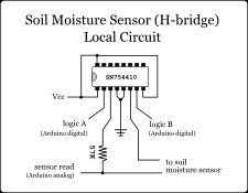
- Remember that you can adjust this sensor by changing the resistor that makes up the other part of the voltage divider (see the local circuit below).
Here is a diagram for constructing the actual probe.
This basic cheap soil moisture sensor consists of two probes (the metal rods) held apart at a fixed distance by some insulating material.
The other factor is that part of the probe is insulated so that you can control at what depth you would like to take the reading.
So, our sensor starts with a 50mm thick (tall) insulating block. This does keep the rods apart, and is also just a booster — it’s a big, foam block sitting on the soil so you don’t accidentally dig up your sensor.
Next down is the insulated section of the probe (also 50mm). From here down, the probe will be under the soil. If you want to change the depth of the reading, you can just change the length of this insulated section. You will not have to make changes to the local circuit.
Finally we have the exposed part of the probe (again 50mm). This is the part of the probe that actually takes the reading. You could experiment with different lengths here, but you will have to make changes to the local circuit (to adjust the voltage divider).
To make the probes, cut two pieces of galvanized wire — each 200mm (20cm) long. Of course if you have cut this wire from a roll, you will need to straighten it.
Next, you will need to solder a lead wire to one end of each probe wire — this will be the top end. Make sure to give yourself enough wire to work with when you bury the sensor outside (maybe 75 to 100cm, around one yard).
We want each probe to be insulated for most of its length — notice in the diagram above that only the last 50mm of the probe is exposed metal.
Now that you have the probe with the lead wire attached, you can insulate the thing by using heat-shrink tubing (see heat-shrink).
Cut a block of the packing foam to make the top of the sensor. When selecting a foam, look for one that is pliable enough to accept the sensors being jammed through it (sometimes styrofoam is a problem).
In this photo the block is 70mm wide, 50mm high, and as thick as the sheet I cut it from.
Mark on the block, on both top and bottom, where you will stab the sensors through. Use the awl (etc.) to make two holes that are parallel — you may want to stab through from each side.
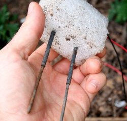
And here is the sensor once it is buried in the soil. Note the wires for the soil temperature sensor to the left of the foam block.
This is the sensor after perhaps one month of use. Notice that the leads have begun to corrode somewhat. But the readings are still very accurate.
Different types of soil moisture sensors
There are several different types of soil moisture sensor out there. The Wikipedia article on soil moisture sensors explains some of the different types.
You might also want to check out the sensor from Vegetronix (VG400). I will report more — I am in the process of testing one myself. Though initial tests indicate that our basic cheap sensor has nearly as much accuracy and somewhat better dynamic range.
The type of sensor we are building in this module is a resistive sensor. The resistive type of moisture sensor is the most crude. It uses the two probes to pass current through the soil, and then we read that resistance to get the moisture level. More water makes the soil conduct electricity more easily (less resistance), while dry soil conducts electricity more poorly (more resistance).
For more detail: The Soil Moisture Sensor