No it’s not a name for some obscure industrial goth band… though that would be sick af!
Anyway, If you ever used a graphics tablet to draw, paint or sculpt, you know how awkward it can be to click and drag something precisely with a stylus. You place it down or lift it up and the cursor position has moved because your down-motion was at a slight angle. It’s a huge pain, even If you got rid of the annoying windows pen & touch circle.
Let’s say you were working in Photoshop and wanted to nudge a color slider value by a couple of clicks in one direction and be precise about it.
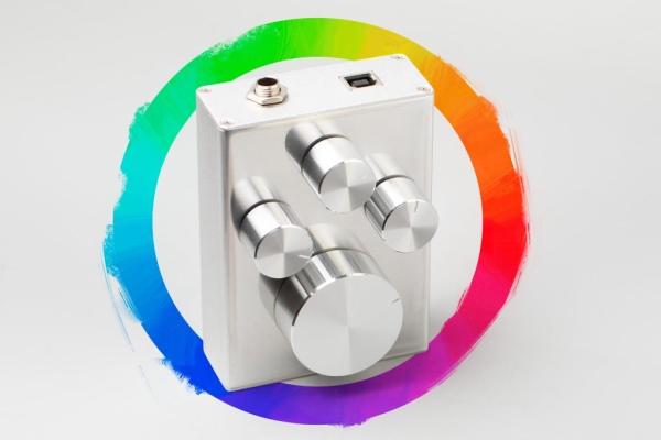
This is a tool for that.
It allows you to select three different sets of sliders (RGB, HSB and Lab) and adjust them with a high degree of precision. As a painter I find Lab sliders particularly useful, even if you’re working in RGB space, because it’s based on opponent color model and allows to adjust color not in absolute sense, but rather intuitively by shifting it towards blue or yellow (b), red or green (a), all while the lightness value stays mostly the same, adjusted by the L slider.
I am focusing on Adobe Photoshop because it’s the industry standard for digital painting and that’s what I personally use. I will be assuming that for the most part you know how to use a soldering iron, know how basic electronic circuits work and how to upload a piece of code to an arduino board using Arduino IDE, all very simple stuff.
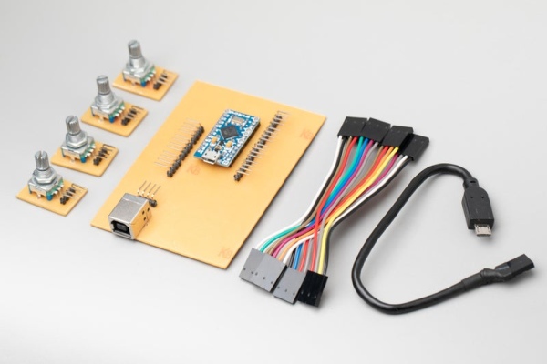
Step 1: Essential Parts
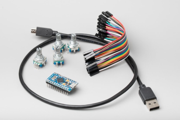
- Arduino Pro Micro clone (or possibly any other board that supports keyboard over USB)
- Mechanical rotary encoder with a push button (4x)
- Some dupont jumper wires (or any suitable wires, really)
- USB cable
Step 2: Encoder Wiring
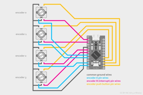
This is the essential wiring required for the project to work. How you do it is entirely up to you. You can solder wires to the components directly, you can use pin headers for connecting/disconnecting parts like I did or you can come up with some cool way to mount everything including encoders on a single PCB, I don’t know. If you’re using a different type of board, just make sure you have at least one interrupt pin per encoder.
Step 3: (Optional) Non-essential Wiring
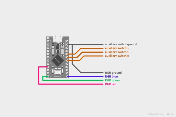
This is more of a suggestion on how to use up the remaining arduino pins, if you want to. You could add some RGB underlighting using the PWM pins (here’s an one example of driving an LED directly and another one that uses N-channel MOSFETs), you could also wire up some jack sockets to connect auxiliary switches, for example the foot switches commonly sold as piano sustain pedals.
Step 4: (Optional) Non-essential Parts + Making PCBs
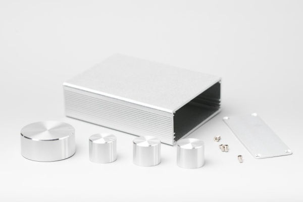
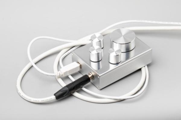
You might want to consider getting a suitable enclosure and potentiometer knobs
for the encoders, based on what is available and what you like. I got this aluminium box and knobs at my local electronics store.
Additionally you could get some pin headers/sockets of your choice to make custom cables, add a jack socket for auxiliary switches or even an objectively superior USB port to adapt the horrible, horrible micro USB of the arduino.
The rest is even more optional and depends on your enclosure of choice (or lack thereof). My enclosure had a slot for a 7x10cm PCB, so I made one to mount the arduino, adapt the USB port to Type-B and keep everything tidy. I made tiny additional boards to mount the encoders in, this is also optional as you can solder directly to encoder leads or even buy them with similar boards already attached.
PCB making is outside the scope of this instructable, but here’s a good intro. There are also online companies that make PCBs, as I’m sure you are aware.
To make it short, I’ve designed the PCB layout using the free version of Autodesk Eagle. For the board itself I used a pre-sensitized single-sided FR2 board. To transfer the layout I used an inkjet printer with regular office paper, soaked in vegetable oil for the exposure to make it transparent. As I don’t have a UV exposure unit, I used my photographic studio flash pack for a total of 3 flashes, 3000J each, but leaving it in the sunlight for a bit would have done the job too. I used caustic soda as developer, sodium persulfate as etchant, and acetone to remove the remaining photoresist. I marked the holes using a punch and drilled it using a cordless drill (super not ideal, wish I had a drill press). I didn’t have any liquid tinning solution or solder resist, so I soldered everything to bare copper and after cleaning the board with isopropyl alcohol, I sprayed it with protective varnish (PRF 202) to prevent oxidation and corrosion. No, I’m not going to show my soldering, trust me it’s atrocious.
Step 5: Assembly
Yours will obviously be completely different, so here’s how mine went:
Putting everything together was a bit of a challenge and often felt like solving a puzzle. Mounting the encoders, connecting all the pin headers and inserting the main PCB had to be done in a very specific order to work. While drilling the encoder holes I had an oopsie and badly scratched the top of my enclosure, so I decided to try sanding and polishing it as best as I can. It’s far from perfect but I actually think it looks better than the original matte surface, even if it is a huge fingerprint magnet now. Drilling and filing out the square hole for USB port required a lot of patience but I think I’ve done a decent job.
Step 6: How It Works + Programming Arduino
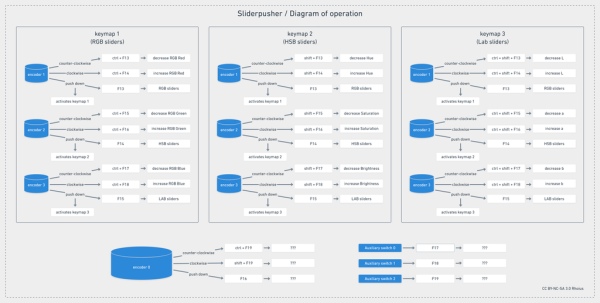
I’ve programmed it so there are 3 “keymap” settings that affect the keystrokes sent by encoders 1-3 (see diagram), while encoder 0 and (optional) auxiliary switches are independent.
There are many ways to get arduino to read rotary encoders, most of them rely on encoder pulse triggering some kind of interrupt service routine (ISR). There are multiple libraries that support encoders, but I didn’t find it necessary for my build. Pro Micro has only 4 interrupt pins, so I used one for each encoder. During an interrupt condition it checks if the interrupt pin reading has actually changed from the last known state to help with debouncing, then it compares the readings from both pins to determine the rotation direction and updates the pulse count variable. I found that the encoders I have generate 40 pulses per one full rotation this way, while only clicking 20 times, so to get the final rotation variable I divide the pulse count by 2.
The main program loop constantly checks for changes in encoder rotation and switch positions, then activates appropriate pieces of code to send keystrokes via USB.
I chose to use F13-F24 keys because they actually exist and are very rarely bound to any command, in any software. This avoids conflicts with already existing hotkey combinations, but you can also easily change these keybinds to whatever best suits you.
Grab the code below and upload it to your arduino board:
Step 7: Getting Photoshop to Behave
Photoshop is an old and clunky piece of software, where some of the most useful commands can’t be accessed with keyboard shortcuts directly. A lot can be done with Actions, for example making an action to select a specific brush and assigning a keyboard shortcut to that action, however Actions have their limitations too, and often either record something too specific or don’t record what you do at all. Fortunately, photoshop supports custom scripts, which, when placed in Photoshop’s \Presets\Scripts\ directory, can be activated with a keyboard shortcut.
If one wants to adjust a component slider for current (foreground) color, the “script” usually consists of one line of code (or two if you want to add an if statement to prevent it from going over a certain value), for example here is a full script to move the HSB hue slider up by one:
app.foregroundColor.hsb.hue++;
You can write your own scripts like this in notepad and save them as .jsx files in your scripts directory or you can grab the ones I made from GitHub.
The only problem with this workaround is that Photoshop accesses the script file from disk every time you press the keyboard shortcut. This is not ideal and can potentially slow things down if you trigger too many of them at once, but it works well enough for small, precise adjustments.
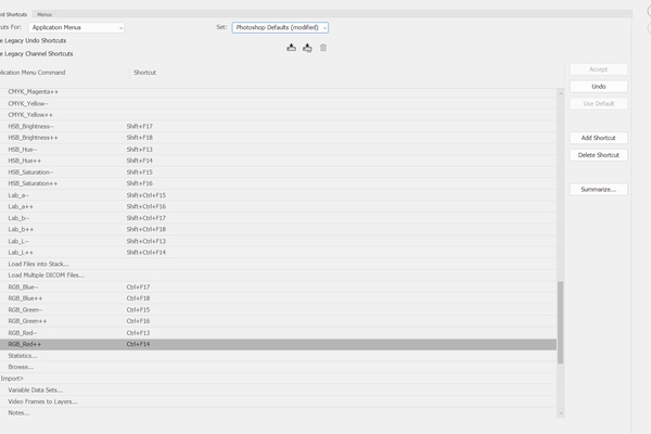
After you copy the scripts and restart Photoshop, you should be able to assign keyboard shortcuts to them. That can be done by going to Edit>Keyboard Shortcuts… and finding your script names under panel menus>file>scripts. Just operate the encoders to assign appropriate key combinations.
While I designated encoders 1-3 to do specific functions, what encoder 0
does in Photoshop is up to you. I personally use it for scrolling through document history states, but you could easily use it for layer selection, brush selection, brush size adjustment, etc.
Step 8: Possible Future Upgrades
For any production work I’d upgrade the encoders to higher quality more durable ones. The ones I have seem somewhat flimsy. Additionally I want to add some rubber feet and maybe re-polish the enclosure for a better surface finish. Might even add the RGB underlighting as well.
I’m also thinking about ways of using this thing in other software, like ZBrush, or even writing a simple MIDI controller code for use with digital audio workstations. I’ll update this instructable as I figure it out.
Step 10: Wait, Isn’t This Just a Button Box With Extra Steps?
yes.
If you liked this instructable, please consider showing solidarity and donating to your local trans charity or getting involved in activism for trans rights directly <3
Source: Sliderpusher for Digital Painters