Summary of How To Simulate Arduino With Proteus
This article outlines the process of integrating Arduino boards into Proteus ISIS simulation software. It details downloading and installing specific library files, configuring system settings within Proteus, compiling code in the Arduino IDE to generate a .HEX file, and linking that file to the virtual board for circuit simulation. The guide uses an LED blink example to demonstrate the complete workflow from setup to execution.
Parts used in the Arduino Proteus Simulation:
- Proteus ISIS
- Arduino Library Files (ARDUINO.IDX and ARDUINO.LIB)
- Windows Explorer
- Arduino Software (IDE)
- .HEX File
- LED
Some Arduino boards can added to the most common and powerful simulation software for electronics hobbies which is Proteus from Labcenter Electronics. Here are steps for adding Arduino library for Proteus ISIS.
Step 1: Download the following zip file DOWNLOAD
Step 2: Extract the zipped file and you will find two files ( ARDUINO.IDX and ARDUINO.LIB ).
Step 3: Open Proteus ISIS and go to System —> System Settings
Then you will get the following window, right click at Library folders: and choose Browse in Windows Explorer, and that folder will opened then copy both two files you get (ARDUINO.IDX and ARDUINO.LIB) to that folder.
Step 4: Restart Proteus ISIS and search for Arduino or simply go to Emulator
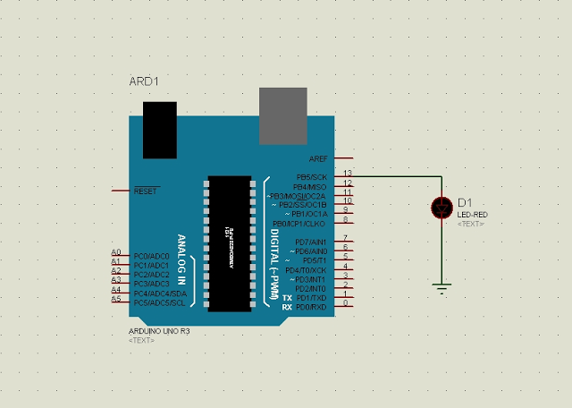
For example I am going to simulate LED blink circuit on Proteus, the circuit is as shown above:
Step 6: Run Arduino software and go to File —>:
Step 6: Run Arduino software and go to File —>:
Then you will get the following window just check compilation which allows the Arduino IDE software to generate and save .HEX file of the code.
Step 7: Write your code and click on Verify then copy (CTRL + C) the address of the HEX file as shown below:
Return to your circuit in Proteus ISIS and double click on the Arduino board and past what you have copied as shown on the following image:
Step 8: Simulate your circuit ………… enjoy!!
Arduino Proteus simulation example:
Let us return to our LED blink example, the circuit is shown above and the code is from Arduino examples:
Arduino Proteus simulation example:
Let us return to our LED blink example, the circuit is shown above and the code is from Arduino examples:
/*
  Blink
  Turns on an LED on for one second, then off for one second, repeatedly.

  This example code is in the public domain.
 */

// Pin 13 has an LED connected on most Arduino boards.
// give it a name:
int led = 13;

// the setup routine runs once when you press reset:
void setup() {
  // initialize the digital pin as an output.
  pinMode(led, OUTPUT);
}
Read More: How To Simulate Arduino With Proteus
- How do I add the Arduino library to Proteus?
Download the zip file, extract ARDUINO.IDX and ARDUINO.LIB, then copy them to the Library folders directory via System Settings. - What files are required for the installation?
The installation requires two specific files named ARDUINO.IDX and ARDUINO.LIB extracted from the provided zip archive. - Can I simulate an LED blink circuit on Proteus?
Yes, you can simulate an LED blink circuit by following the steps to install the library and load the compiled HEX file. - How do I ensure the Arduino IDE generates a HEX file?
You must check the compilation option in the File menu of the Arduino software to allow it to generate and save the .HEX file. - Where do I find the address of the generated HEX file?
After verifying your code in the Arduino software, you copy the address of the HEX file as displayed in the output window. - How do I link the code to the Arduino board in Proteus?
Double click on the Arduino board in your circuit and paste the copied HEX file address into the configuration field. - Do I need to restart Proteus after adding the library?
Yes, you must restart Proteus ISIS after copying the library files to the correct folder. - Which pin is used for the LED in the example code?
The example code initializes digital pin 13 because most Arduino boards have an LED connected to this pin.