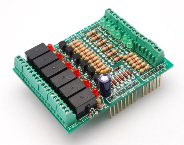
Shield to control 6 relay, 6 digital input and 6 analog input with Arduino Duemilanove, Arduino UNO. The digital inputs and relay outputs are equipped with an LED that indicates the status.
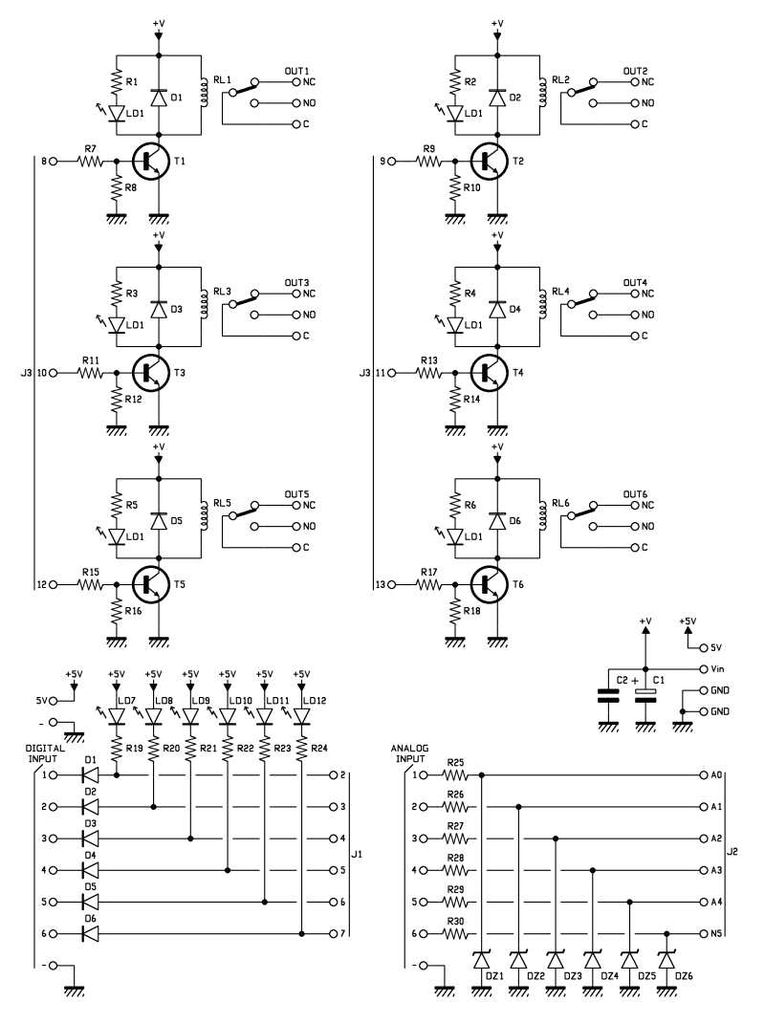
The circuit diagram is very simple:
Step 1: Schematics and PCB
In this step you can find the circuit diagram and the PCB file.
All the digital input are protected by a diode, the analog input are protected by a zener diode.
BOM Arduino – IN/OUT
R1: 1 kohm
R2: 1 kohm
R3: 1 kohm
R4: 1 kohm
R5: 1 kohm
R6: 1 kohm
R7: 4,7 kohm
R8: 10 kohm
R9: 4,7 kohm
R10: 10 kohm
R11: 4,7 kohm
R12: 10 kohm
R13: 4,7 kohm
R14: 10 kohm
R15: 4,7 kohm
R16: 10 kohm
R17: 4,7 kohm
R18: 10 kohm
R19: 470 ohm
R20: 470 ohm
R21: 470 ohm
R22: 470 ohm
R23: 470 ohm
R24: 470 ohm
R25: 4,7 kohm
R26: 4,7 kohm
R27: 4,7 kohm
R28: 4,7 kohm
R29: 4,7 kohm
R30: 4,7 kohm
C1: 100 µF 25 VL el
C2: 100 nF
D1: 1N4148
D2: 1N4148
D3: 1N4148
D4: 1N4148
D5: 1N4148
D6: 1N4148
D7: 1N4148
D8: 1N4148
D9: 1N4148
D10: 1N4148
D11: 1N4148
D12: 1N4148
DZ1: Zener 5,1V 400 mW
DZ2: Zener 5,1V 400 mW
DZ3: Zener 5,1V 400 mW
DZ4: Zener 5,1V 400 mW
DZ5: Zener 5,1V 400 mW
DZ6: Zener 5,1V 400 mW
LD1: Led 3 mm red
LD2: Led 3 mm red
LD3: Led 3 mm red
LD4: Led 3 mm red
LD5: Led 3 mm red
LD6: Led 3 mm red
LD7: Led 3 mm green
LD8: Led 3 mm green
LD9: Led 3 mm green
LD10: Led 3 mm green
LD11: Led 3 mm green
LD12: Led 3 mm green

T1: BC547
T2: BC547
T3: BC547
T4: BC547
T5: BC547
T6: BC547
RL1: mini relay 12V
RL2: mini relay 12V
RL3: mini relay 12V
RL4: mini relay 12V
RL5: mini relay 12V
RL6: mini relay 12V
Misc:
– Screw connector 2 via 2,54 mm (8 pz.)
– Screw connector 3 via 2,54 mm (6 pz.)
– Strip 8 via 12 mm (3 pz.)
– Strip 6 via 12 mm
– PCB
For more detail: Simple Relay Shield for Arduino

