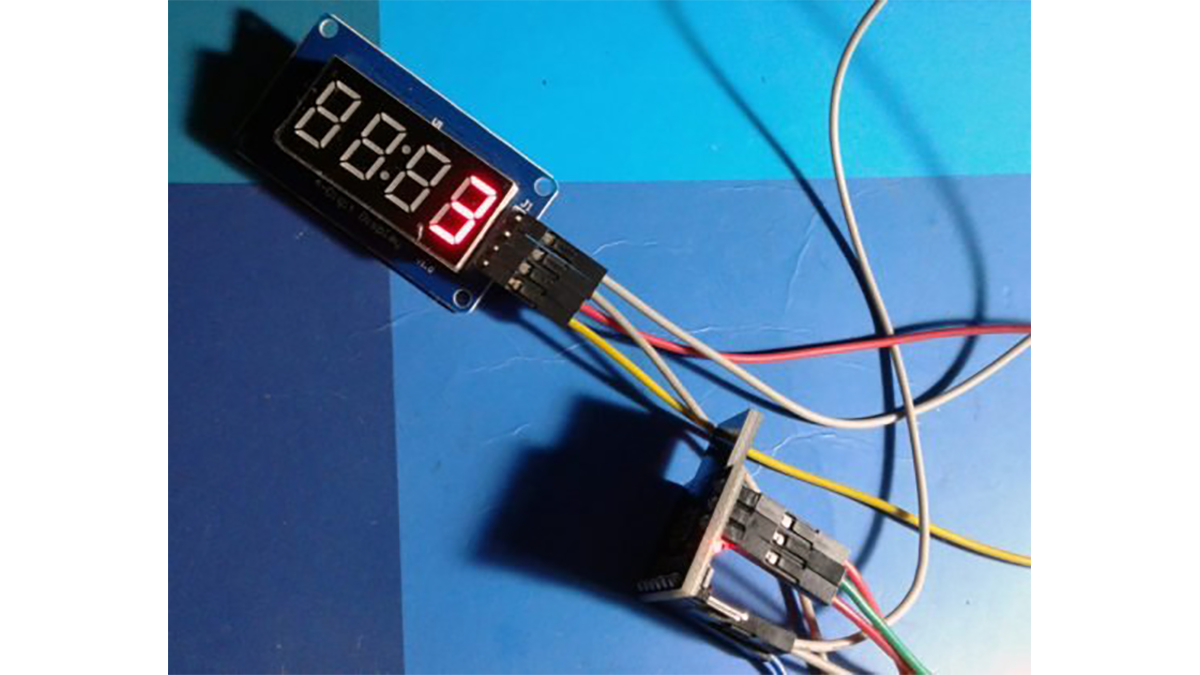
The miniscule event counter based on a microcontroller is built using the affordable Digispark Attiny development board. A benefit of this design is that it can be connected to its trigger input regardless of whether it is an active or passive switch. Every time the switch is turned on, the microcontroller will count the event and show it on the 4-digit TM1637 LED display module. The circuit can be powered by any 9V dc source that can supply at least 500mA of current to the device it is connected to. There are practically endless possibilities with this digital event counter!
Event counter hardware overview

Microcontroller
The Digispark Attiny85 is a useful microcontroller for basic projects. The authentic and counterfeit versions both have a pre-installed micronucleus bootloader. The micronucleus bootloader enables us to upload code to the ATTINY85 using a USB connection. The information can be found in detail on the digistump site (https://digistump.com/wiki/start).
Digital Display
As mentioned, the heart of the display module is the TM1637, a unique LED driver/controller chip from Titan Micro Electronics (www.titanmec.com). TM1637 only needs a two-wire bus interface (CLK & DIO) to communicate with any microcontroller. It should be mentioned that this form of communication differs from the well-known 12C bus protocol in that it lacks a slave address, and an acknowledgment signal (ACK) is internally produced within the chip for proper data transfer.
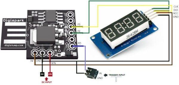
Besides these two crucial components, only a small number of separate elements are needed to finish the hardware configuration. Take a look at the visual representation of the event counter displayed underneath.
Software Inside
Similar to the hardware, the software is also uncomplicated, consisting of just a few lines of code. An important library called “TM1637Display” is provided as it is essential in this case. The well-documented code presented can be managed using Arduino IDE (version 1.6.9). Simply paste the code, compile it, and upload – it’s as easy as that. Please be aware that the TM1637Display library can be added to the Arduino IDE like any other library, simply by placing the files in a designated directory within the Arduino IDE’s library search path.
[stextbox id=”grey”]/* Simple Event Counter
* Using TM1637 LED Display
* uC: Digispark Attiny85
* Prepared by T.K.Hareendran
*/
#include
#include //essential library from avishorp
#define CLK 2 // clock
#define DIO 3 // data i/o
#define TEST_DELAY 2000
TM1637Display display(CLK, DIO); //setup the display
void setup()
{
pinMode(0,INPUT); // counter trigger input pin
digitalWrite(0,HIGH); // enable internal pull-up
display.setBrightness(6); // brightness level 0-minimum, 7-maximum
}
int numb=0;
int pres=0;
void loop()
{
display.setBrightness(0x0f);
display.showNumberDec(numb,false); // function to display numbers upto 9999
if(digitalRead(0)==0) // read counter trigger pin
{
if(pres==0)
{
numb++;
pres=1;
}
}
else
{
pres=0;
}
}
Pre-Flight Test
Once the buildup is complete, attach a normally-open (N/O) push button switch to the trigger input socket, turn on the circuit, and wait for five seconds. Following the first pause, the digit zero (0) will appear on the LED display furthest to the right. Press the push button switch now, and make sure the counter increases with each button press. If you have reached this stage, it is certain that your event counter is working properly. Begin counting and have fun!
Enhancement
As you observed, almost all normally-opened mechanical switches (like tactile switch, reed switch,etc) can be connected to the trigger input of this event counter without any circuit modification. Active switches (a hall sensor, for example) with open-collector outputs can also be connected in this way. No additional resistors are necessary here because the trigger input (P0 of digispark) is pulled-up by an internal resistor of about 25K value (see the code). However, if you want to trigger the event counter from any active switch/sensor with a logic-high level output, an add-on circuit is required. Here is a cheap’n’cheerful solution to accept active-high (H) signals from the external world.
Download Source Folder
Check out the working of this project here.
Read More Detail :Simple Event Counter


