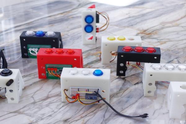
One thing that I’ve always needed for my projects is a simple form of input and output. At first, it was a simple push button and an led on a breadboard. The breadboard mounted buttons are inconvenient. So I created a 3D printed stand to hold an arcade button. Because some arcade buttons came with LEDs (and a built in resistor) it was a natural to use them as an output. These work great for Arduino and simple projects. As the projects (and processors) grew in complexity, I2C (Inter-Integrated Circuit) provided a solution.
This instructable describes a common configuration that I have used in dozens of projects. It will describe two different communication methods, direct and I2C. It use arcade buttons and pre-made wiring harnesses.
This instructable will describe how to build several different versions of a button pad. There are STL files provided for two different styles of mounts, freestanding and a version that is meant to attach to an aluminum extrusion like 80/20. The mounts are sized for 30mm or 24mm buttons.
This project will require access to a 3D printer and some soldering skills.
Supplies
https://www.adafruit.com/product/3657
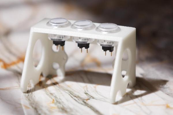
Step 1: Print the Frame
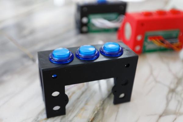
Before you can start on the electronics, download the approprate file for the use and size of button and print it.
The freestanding frames can also be attached to an extruded alumunim beam.
Three 30mm Button freestanding: www.thingiverse.com/thing:3172573
Three 30mm Button 8020: www.thingiverse.com/thing:3172579
Three 24mm Button freestanding: www.thingiverse.com/thing:3172579
Three 24mm Button 8020: www.thingiverse.com/thing:3172579
Step 2: Selecting the Parts
First decide on the button size and color to be used in the project. Decided if the buttons should be illuminated. (Note, not all colors of illuminated buttons work at 3.3V. The 12V buttons require additional circuitry to make work. Check the product description or the data sheet.)The following buttons have been tested and have worked for us.
Arcade Button with LED – 30mm Translucent Clear: www.adafruit.com/product/3491
Arcade Button with LED – 30mm Translucent Blue: www.adafruit.com/product/3491
Arcade Button with LED – 30mm Translucent Green: www.adafruit.com/product/3491
Mini LED Arcade Button – 24mm Translucent Clear: www.adafruit.com/product/3491
Mini LED Arcade Button – 24mm Translucent Blue: www.adafruit.com/product/3491
There are other sources of arcade buttons, such as Amazon and AliExpress.
To complete the button wiring, pick up some arcade wire harnesses. The one listed below has a common ground cable and individual cables for the button and LED.
2.8mm Interface Wires to LED Push Button for Arcade Game www.amazon.com/Easyget-Interface-Button-Arcade-Machine
Or you can use the SparkFun QWIIC buttons. (See the description in step four for more information)
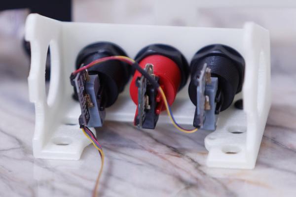
Step 3: Direct Wiring
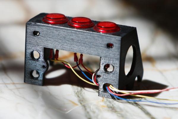
This is the most basic version. You attach the buttons to wires and mount them to the printed button holder. The wires are directly attached to your project. If the button has an LED, it can be attached too.
Some things to think about.
- Check the voltages your project uses. Some colors of LEDs will not work at 3.3V.
- Check to make sure the LEDs in the button are protected by a current limit resistor.
- Arcade buttons are bouncy; really really bouncy. Your code should take this into account. See debouncer-library-python for more information.
- The arcade button cables are a lot easier to use to connect to the buttons. Trying to solder directly to the buttons can be difficult. www.amazon.com/Easyget-Interface-Button-A…
For more information:
Arduino
www.instructables.com/Plug-and-Play-Arcade…
CircuitPython
learn.adafruit.com/arcade-button-control-b…
Step 4: If You Decided to Just Use SparkFun Arcade Buttons.
Sparkfun, through Spark-x has a nice arcade button with a built in QWIIC connector.
www.sparkfun.com/products/15591
www.sparkfun.com/products/15592
Or just get the switch controller and use your own arcade button.
www.sparkfun.com/products/15586
Three quick notes.
- These are Sparkfun Spark-x devices. So they may not be available or may have moved into the regular product category and have different numbers.
- If I remember correctly, the two colored buttons do not have a built in led. I had to use the stand alone controller on a conventional arcade button to use the led.
- Sparkfun has a great library to support the button controller.
Step 5: Making Your Own Controller Board
A better approach to managing buttons is to use attach them to a remote controller and use I2C to communicate with your project. There are many choices in controllers to select from an Arduino, Arduino Nano, Adafruit Feather all work fine. You can also use GPIO extenders.
For example:
www.sparkfun.com/products/17047
We have been using the Adafruit’s ATSAMD09 Breakout board. It has seven GPIO pins with programmable pullups or pulldowns that make it perfect for this application. It has a three PWM pins and three ADC pins. It can drive a neopixel. It uses a 3.3V logic level so is directly compatible with a Raspberry Pi.
Our standard configuration board is built with:
Adafruit ATSAMD09 Breakout with seesaw www.adafruit.com/product/3657
Adafruit Perma-Proto Half-sized Breadboard PCB www.adafruit.com/product/3657
If you want to make the breakout boards removable or quickly temporarily wire in another component, pick up a couple of 0.1″ Female headers.
Adafruit 36-pin 0.1″ Female header www.adafruit.com/product/3657
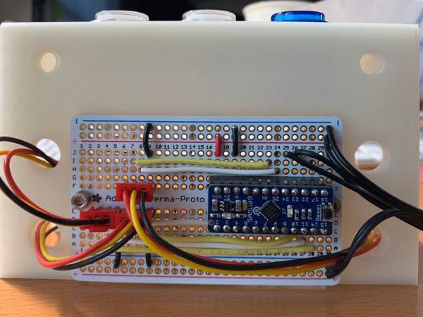
Step 6: An Example of How to Wire Up the ATSAMD09 Using a Perma-proto Board
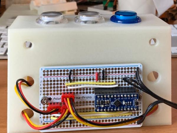
The standard configuration we use for a ATSAMD09 on a Perma-proto board to build a three button illuminated controller is built as follows:
Solder a 12 position female header between G17 – G28 and E17 – E28.
Solder three pin male headers at F(07-09), E(03-05), E(07-09)
Wire:
Note, these are cartiasian coordinates on the permanent-proto board not the PIN numbers on the ATSAMD09.
GND: J19, J09, A05, A09
VIN : J17
I07 : I23
H08 : H24
D08 : D25
C07 : C26
B04 : B27
A03 : A28
J25 : SCL
J26 : SDA
For your connection to an I2C cable you will need VIN, GND, SCL and SDA.
There are still a lot of open pins on the ATSAM for your expansion.
Step 7: A Handy Circuit Board for the ATSAMD09
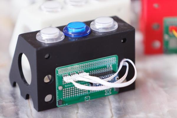
After I wired up a couple of dozen controller boards, I got tired of it. So I designed a circuit board that took care of the tedious parts of using the ATSAMD09 breakout board.
To use this you will need to solder the QWIIC connectors to the board. They are SMD parts, but are fairly large as SMD parts go. Our go to article about SMD soldering is www.sparkfun.com/tutorials/59 The EGALE files for the board are provided. The board is based on the footprint of an Adafruit permanent-proto. The files will need to be loaded into EAGLE to produce the Gerber files to upload to a board house.
The SMD QWIIC headers can be found at:
www.sparkfun.com/products/14417 or
You will need to solder in three 3pins headers to attach the button cables.
You will also need to solder in two 14 pin female headers to support the ATSMD09.
Source: Simple Arcade Button Ideas for Your Projects