Hello,
Here is a simple hexapod that can be built by hand very quickly. The mechanical design is not great, but it is very much in the KISS (keep it stupidly simple) style and should be doable in a weekend for builders of novice to medium experience.
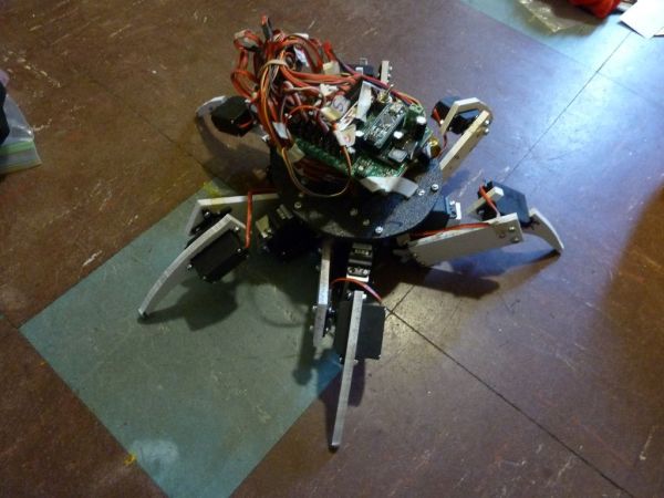
I won’t be improving this project any time soon, and people seem to visit my blog from pololu, so I thought I’d go ahead and document it as is. I built this for a sophomore mechanical engineering class at MIT. The wires and six legs make it look complicated, but since the legs are just the same thing repeated 6 times, it’s simpler than it appears. Additionally, I did not implement remote controls so all the code runs autonomously (zero input, multiple output system).
Again, this is documentation of the exact steps involved in a semi-working project. No theoretical underpinnings for designing your own hexapod are really explained here.
A complete picture set of the build process exists here: 2.007 Hexapod (Spring 2011). The first few pictures on there are from Aluminum Hexalinkagepod, based off of the Parallax boebot hexapod.
A set of blog posts exists here: http://orangenarwhals.blogspot.com/search/label/hexaringapod
I would specifically recommend this post: http://orangenarwhals.blogspot.com/2011/05/dreaming-of-dancing-hexapods-2007.html
A video explaining the design process in 7 minutes (this instructables goes into the construction but not the design): http://youtu.be/qTh-OGA_LeM
and here is a video of it at the end:
Required items (hardware):
~ Vertical bandsaw (unless you have a lot of patience with a razor)
~ 1/4” plastic sheet (any reasonable thickness such that the plastic is fairly rigid is fine. I used 1/4” ABS)
~ About 6” of
~ 18 R/C servos (I recommend standard size, I’ve seen hexapods with the tiny 9g servos, but I think that it would be hard to cut out the holes for such servos by hand), complete with the “+” shaped servo horns and servo center screws that should come with the kit.
I used 6 Hitec-311 and 12 Vigor VS-2 servos because that was what I could scavenge for.
~ Screwdriver
~ 4-40 bolts and locknuts (about 48 of them), or whatever bolts fit through your servo flange holes (the side holes). At least 3/8” long (enough for the 1/4” plastic or Al and a locknut to fit on there).
~ Drill and drill bit, ideally also a drill press
~ Ratchet or socket wrench for 4-40 bolts
~ Ideally, a vice or clamp
~ Ideally, a horizontal bandsaw
~Optional: Scrap 2×4 wood
~ Measuring instrument, ruler or vastly preferably calipers
~ Optional: Deburring tool
Required items (electronics):
~ Arduino nano + breadboard + male headers (for the servos)
~ Either 6 Y-splitter servo cables or a pololu serial servo controller(because the default arduino library only supports 12 servos). I bought an 24ch one, but obviously didn’t need all 24 ch, not sure why I did that. >.<;; but I am a conservative person and tend to make large purchases just in case. I’m working on fixing this.
I guess another option is to use an arduino mega.
~ Laptop and usb programming cable appropriate for your flavor of arduino
~ Male Headers
~ Jumper wires (or single core wire suitable for breadboards)
~ Potentially some servo extension cables, female-to-female (and you stick headers in them to make them female-to-male) will come in handy.
~ Breadboard (probably a standard 700 point one is best if you are putting the nano onto the breadboard)
~ Battery pack (I recommend a rechargeable battery flavor of battery pack, as the 18 servos are power hungry)
~~ so you could use a 4xAA battery pack and it’d be fine (the servos are nominally 5V servos but they will run fine at 6v, they will just be a bit twitchy because their circuitry/feedback+controls are designed for 5v use), but if they were alkaline batteries (~3000mAh) they would run out after an hour or less of use
~~alternatively, use a LM7805 chip to regulate a lipo battery pack, which runs at 7.4v, down to 5V. These linear power regulators dissipate the extra energy as heat. For how to use one, please google “7805 tutorial”. For instance, see: http://jumptuck.com/2011/11/15/voltage-regulation-friend-7805/.
Time required: 1 weekend if you just follow my design. I encourage you to design your own hexapod though, once you see how easy it is!
What I used also included a 2.007 (that’s a course at MIT) carrier board (looks like https://sites.google.com/site/2007arduino/). This just brings the servo pins out for easy access, as well as has a built in breadboard and a switching power regulator* that can supply up to 3A at 5v, which is probably enough for the 18 servos. It seemed to function a-okay, but my code only ever had 6 servos moving at any given time.
I also made my own battery pack out of some Sanyo UR18650U batteries that were donated to MITERS by Tesla. They are 3.6V, so I made a 2-series, 3 parallel battery pack for a 7.2V 3.3Ah battery pack. This is obviously overkill. At 3.3 Ah and continuously drawing 3A, I could run my hexapod for over an hour. I’ve found that 10-20 minutes is plenty of runtime for hexapod.
*as opposed to a LM7805 linear power regulator, a switching power regulator is much more efficient.
Note:The hexapod CAD files are for Solidworks 2012 and do not detail nuts and bolts, they are for reference only. I also made a diameter versus radius error on the body, so the body is too big.
==
Submitted by MITERS for the Instructables Sponsorship Program.
Step 1: Make the Paper Templates for Femur and Tibia Segments
We’ll be using paper templates to mark out six of the same thing (six legs).
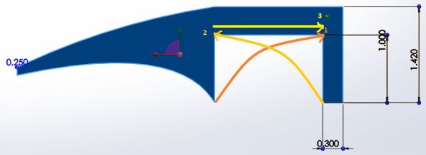
My tibia ended up (after a few iterations) being 1.4×3.75 inches, with holes marked appropriately for where the servo horns would go.
My coxa ended up being 1.42×4.83 inches, with an appropriately sized hole cut out for the servo. The curve on the leg is an arbitrary “it looks nice” curve I cut out directly on the bandsaw (I started out with rectangular legs).
The CAD model you see in the pictures is a later and better (read: smaller and lighter, more appropriate for the servos) revision than the paper templates, and should give you some idea of how it the hexapod is assembled. So ignore the dimensions written on the paper template in the pictures.
Once you are done making the templates, mark them onto the plastic sheet in preparation for cutting. For marking the holes, sharpie bleeds through paper so just line the paper templates up with the plastic and mark the template with sharpie and it should show up on the plastic. I actually cut the legs out and then marked the holes; you can do it in any order.
Step 2: Cut out the Femur and Tibia Segments
I used a vertical bandsaw for cutting out the femur and tibia segments. Make sure to wear safety glasses and take appropriate safety precautions (no loose hair/jewelry/clothing, etc.).
For the tibia and cutting out where the servo fits through, since the bandsaw blade can’t just turn around when you hit the inside corners, instead of one continuous cut, you make two half-moon cuts from opposite sides and then go through and cut the back edge. See the first picture.
Step 3: Drill out the Servo Horns and Leg Segments
The servo horns and should have holes the same size for the bolts to drop through and be locked in place with locknuts. Look up “tap and drill sizing chart” on google, then clearance or through hole fits, for whatever size screw you ended up getting. Basically, the holes should be the major diameter of the screws, so that the body of the screw fits through but not the cap.
For instance, for 4-40 screws (#4 size screws with 40 threads per inch), I look up http://www.physics.ncsu.edu/pearl/Tap_Drill_Chart.html and see that I can use either a size 32 or size 30 drill bit for a clearance hole. Probably I will use a size 32, in case my hole is drilled off-center, I have some leeway for the bolt to still fit through even if the femur/tibia segment holes are not lined up perfectly with the servo flange holes.
To prevent too much burring on the back side and give the vice something thick to clamp on to, I put a block of wood behind the servo horns. These holes can all be done free-form with just a hand-drill because the plastic is so soft, especially with a center drill for the femur/tibia segments, but you just won’t get nice cuts (and be careful not to send things flying if you don’t press down with your hand hard enough). Actually, I really can’t recommend doing it without clamps or a vice, for safety’s sake.
To make it easier the next time around: I would have used self-tapping screws, or perhaps even just normal screws as the plastic is pretty soft, and then drilled sizing for aluminum (75% thread), e.g. for 4-40 I would have used a size 43 bit. This way, I don’t have to deal with the whole locknut thing which takes extra tools and forever to tighten. I would have to have self-tapping screws of the right length, though, since they have pointy ends which might hurt if they stuck out of the plastic.
Yea, locknuts are much better than just two nuts tightened together, which always loosen unless you use locktite, but if you mess up something they take forever to un-tighten and re-tighten.
Step 4: Attach Servos to Femur and Tibia
Time to break out the screwdriver and socket wrench!
I used bins to keep all the servo stuff organized, but that’s entirely optional.I used bins to keep all the servo stuff organized, but that’s entirely optional.
It’s easy to zone out and put one or the other servo horn facing the wrong way or flipped or whatever — again, locknuts are a pain to redo.
Make sure to use the center screw to screw into the servo. This keeps the leg segment from falling off of the servo.
For more detail: Simple 18dof Hexapod, Arduino nano (optionally with pololu maestro)