The Shensuo dress is a piece of wearable technology which allieviates the dress stress of the modern woman; through its range of temperature and humidity sensors assisted by a clock as well as a manual override. Using two small motors built into the bodice attached to the skirt via string, which is pulled to rotate the pleats, Shensuo is capible of adapting to all temperatures (based on external temperature), a set time of day or as required. Further, Shensuo also possesses the means of changing colour, using the same mechanism. Ergo, Shensuo the perfect smart casual dress for any occasion, night or day, warm or cool.

Step 1: Requirements
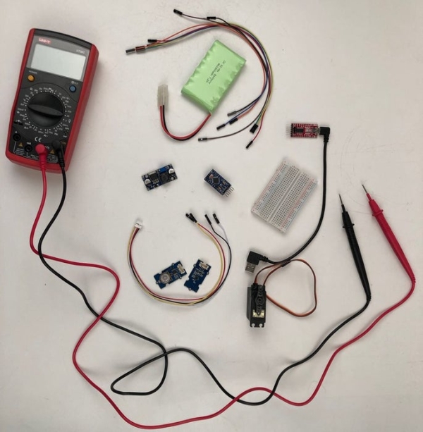
Required Equipment
2. Breadboard – for prototyping
3. Jumper Cables for the breadboard
4. LM2596 – DC to DC transformer or equivalent
6. Grove Temperature and Humidity Sensor
8. USB to Serial Adaptor – for communicating with the Arduino
8. A form of external power source for powering the Servo motors
Step 2: Uploading to the Arduino Pro Mini
If your Arduino has a USB connector you can skip this section.
The Arduino Pro Mini is unlike most normal Arduino boards, in that it does not have a standard USB connector on the board. It relies on some form of USB to serial connection in order to upload code and use the serial monitor.
You can refer to this other instructable by push_reset if you get stuck.
The SparkFun 5v FTDI adaptor is a good choice for the 5v Arduino Pro Mini, and we will be using a variation of it in this tutorial.
NOTE: Your FTDI adaptor should output the correct voltage for your Arduino Pro Mini, the Arduino Pro Mini comes in two variants; the 5v and the 3v3. Ensure that your FTDI adaptor outputs the correct voltage otherwise you risk bricking your Arduino. SparkFun also offer the FTDI adaptor in a 3v3 variant.
Connecting the Board
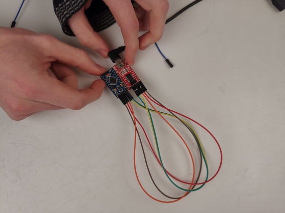
1. The pins on the Arduino Pro Mini that are perpendicular to the the board. With the reset button at the bottom, and the connection pins at the top; they are labelled DTR – TXO – RXO – VCC – GND – GND.
2. With the SparkFun adaptor you can simply slide the Arduino into the pins on the bottom of the board. This project had a slightly different adaptor to the one that I recommend from SparkFun which required us to use jumper cables to connect up the Arduino.
3. Plug the Adaptor, with the Arduino still attached into your computer. The Arduino and the adaptor should light up.
Uploading to the board
1. With the Adaptor and the Arduino connected, open the Arduino IDE
2. Click Tools, and then hover over Port on the dropdown menu
3. Select the FTDI adaptor from the list, it may appear as a serial device or a COM port
4. On the Tools menu bar, you will need to ensure that the correct Board has been selected, hover over board and select “Arduino Pro or Pro Mini”
5. The Arduino Pro Mini also comes in a number of variants, so you will need specify the processor being used. This is usually indicated on the back of the board. The processor name is printed on the black square on the board, in my case this was ATMEGA328p. The second piece of information you will need is the voltage of the board, this should be indicated on the back. Once you have this information you can select the processor and voltage in the menu.
If you get this wrong nothing problematic will happen it just won’t upload any code, if this happens just try another one of the processor options until you can upload.
5. Now, on the menu bar; click File and then Examples -> Basics -> Blink
6. Upload the sketch by clicking the right pointing arrow at the top left of the Arduino screen.
7. The sketch should upload correctly and a light should have started to continuously blink on your Arduino
Step 3: RTC – Clock Setup
Arduino’s and other microcontrollers cannot track the current time of day. To enable our project to maintain the current time we will be using the Seeed Grove – RTC.
In this tutorial we will be using the Makuna’s RTC. The library is available from the Arduino library manager, and this will be the way we download the required files. You can also access the library from GitHub.
Installation Method
1. Open the Arduino application
2. Navigate to Sketch -> Include Library -> Manage Libraries
3. In the search box, type “RTC Makuna” and it should be the only result
4. Install the library and wait for everything to finish.
Board Setup Method
In this project we used a normal Arduino without the Grove headers, we grabbed a couple grove to pin connector cables for attaching and prototyping with our board.
If you have a board with a grove connector such as the Seeeduino or a Grove Shield, like this one for the Arduino Mega, you can just use the cables in the box to connect up the board. Refer to this tutorial for further assistance.
If you’re like me and just have a regular Arduino, keep reading.
NOTE: A4 and A5 are the i2c pins for the Arduino Pro Mini, they will be on different pins on different boards so make sure to check that you have the
1. The Arduino Pro Mini has two i2c pins at A4 and A5, A5 is the SCL connection and A4 is the SDA connection – See this reference Image
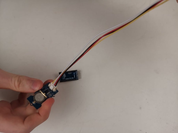
2. Take your Grove to 4pin splitter, plug the grove end into the RTC clock.
3. Attach the red cable to the 5v or the vcc pin on your Arduino
4. Attach the black cable to one of the grounds on the Arduino, labelled as GND.
5. Attach the yellow cable to A5, and the white cable to A4.
Testing the Board
Now you’re ready to upload some code, refer to the previous slide on uploading to the Arduino Pro Mini if you’re stuck at this stage.
With the library from Makuna installed, a number of examples were also installed which can be used for testing the device.
1. On the menu bar, click file and then examples
2. Towards the bottom of the list will be RTC Makuna, hover over this option and select DS1307_Simple from the list.
3. Upload the sketch to the Arduino by pressing the horizontal arrow on the top left of the screen. If you encounter any uploading issues, refer to the previous step.
4. Now you want to view the output of the board, open the serial monitor by pressing the magnify glass on the top right of the Arduino screen, or by clicking Tools and then Serial Monitor. If there is no output, or strange characters are printing to the screen; it is very likely that the selected baud rate is incorrect, on the bottom right of the serial monitor screen, click where the word baud appears. The Arduino Pro Mini has a default baud rate of 57600, select this from the list and text should appear on the screen. The correct time should be displayed.
FAQ
Output from the clock is some variation on 165. This is usually because the board is receiving insufficient voltage. I found that 5v based boards will result in a smoother operation than their 3v3 counterparts, if you have a 3v3 board I would recommend either finding the 5v variant of the Pro Mini or stepping up the voltage.
Other Resources
1. Adafruit’s Guide to Connecting the board to the arduino
Step 4: Temperature Sensor Setup
The installation of the temperature sensor is largely similar to that of the RTC clock. In this tutorial we will be using the Seeed Grove Temperature and Humidity sensor. Seeed has a tutorial here, but it relies on you having a header board for the Arduino, which we did not use in this tutorial.
Installation Method
1. Open the Arduino application
2. Navigate to Sketch -> Include Library -> Manage Libraries
3. In the search box, type “TH02” and it should be the only result
4. Install the library and wait for everything to finish.
Board Setup Method
It is assumed that you have a Grove splitter cable like this one.
NOTE: A4 and A5 are the i2c pins for the Arduino Pro Mini, they will be on different pins on different boards so make sure to check that you have the
1. The Arduino Pro Mini has two i2c pins at A4 and A5, A5 is the SCL connection and A4 is the SDA connection – See this reference Image
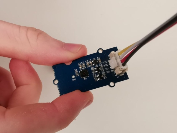
2. Take your Grove to 4pin splitter, plug the grove end into the temperature sensor
3. Attach the red cable to the 5v or the vcc pin on your Arduino
4. Attach the black cable to one of the grounds on the Arduino, labelled as GND.
5. Attach the yellow cable to A5, and the white cable to A4.
Testing the Board
1. On the menu bar, click file and then examples
2. Towards the bottom of the list will be “Grove Temper Humidity TH02”, hover over this option and select the demo
3. Upload the sketch to the Arduino by pressing the horizontal arrow on the top left of the screen. If you encounter any uploading issues, refer to the previous step.
4. Now you want to view the output of the board, open the serial monitor by pressing the magnify glass on the top right of the Arduino screen, or by clicking Tools and then Serial Monitor.
FAQ
If there is no output, or strange characters are printing to the screen; it is very likely that the selected baud rate is incorrect, on the bottom right of the serial monitor screen, click where the word baud appears. The Arduino Pro Mini has a default baud rate of 57600, select this from the list and text should appear on the screen. The correct time should be displayed.
Step 5: Servo Setup
The Servo’s in this garment will be used to shift the pleats between their colours. For this project we used the TowerPro 5010 Servo, available from Adafruit here.
Servo’s require a significantly higher current draw than the Arduino, and most Arduino’s cannot support this fluctuation when the Servo is under load. The Servo has to be powered externally to the Arduino to ensure that the voltage does not fluctuate across the Arduino.
Requirements
– DC to DC transformer – we used the LM2596 board – this will ensure that the output voltage is steady for our Servo’s. This will also scale down any input voltage to our required voltage that we will set.
– An External power source – We used a 7.2v 2000mah battery
– Flat head screwdriver
– Multimeter to measure the output voltage of the DC to DC transformer
– Jumper Cables
– Breadboard
External Power Supply
The external power supply should be greater than 5v, this can be supplied by a battery.
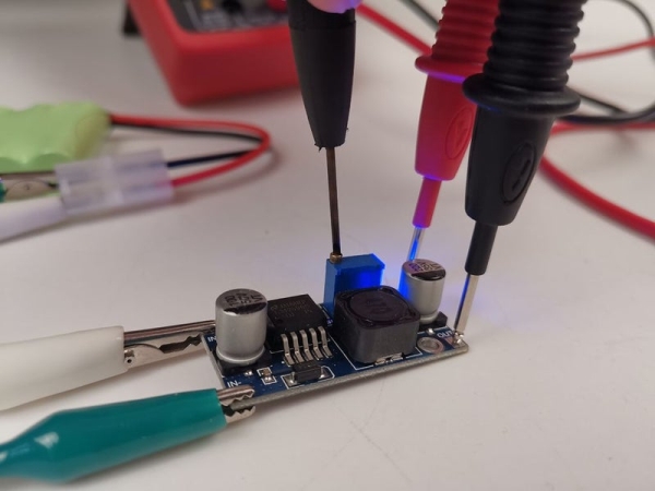
Setting up the Transformer
1. Connect the positive and negative connections of your external power supply to the input pins on the DC to DC transformer
2. Turn on your multimeter and set it to the voltage setting
3. Connect the contacts of the multimeter to the output of the transformer
4. Now take your screwdriver.
5. The servos have a max voltage of 6v, the reading on the multimeter should be below this value
6. Turn the golden knob on the transformer until the multi-meter reads a value below 6v, try to approach 6v without exceeding it
Connecting the Servos
1. Take your Arduino, connect one of the ground pins to the negative rail on the breadboard.
2. Connect the negative output of the transformer and connect it to the same rail on the breadboard.
3. Take your servo, connect its ground pin, either black or brown, to the same rail. The servo, external power and the Arduino must all share the same ground.
4. The positive output of the transformer should connect to the servo power (red).
5. Connect the white/yellow signal pin on the servo to pin 9 on the Arduino Mini Pro
Testing the Board
1. Open the Arduino IDE
2. Click File on the menu bar -> Examples -> Servo -> Sweep
3. Upload to the Arduino and the Servo should move backwards and forwards
Step 6: Putting It All Together

The final step of the process is to combine all of this together in order to trigger the servos with the temperature and clock sensors.
The final code is available here on my GitHub.
Source: Shensuo