Summary of Servo Motor Control by Flex Sensor
This tutorial details a project to control a servo motor's shaft position using an Arduino Uno and a Flex sensor. The system interprets the Flex sensor's resistance changes, caused by bending, into voltage variations via a voltage divider circuit. An Arduino ADC converts this analog voltage into a digital value, which determines the PWM duty cycle sent to the servo motor, thereby adjusting its angle based on the degree of flex.
Parts used in the Servo Control System:
- FLEX sensor
- Arduino Uno
- Servo motor
- Voltage divider circuit
- Constant resistance (R1)
- Analog to Digital Conversion (ADC) feature
In this tutorial we are going to develop a circuit using FLEX sensor, Arduino Uno and a Servo motor. This project is a servo control system where the servo shaft position is determined by the flex or bent or deviation of the FLEX sensor.
Lets first talk a bit about servo motors. Servo Motors are used where there is a need for accurate shaft movement or position. These are not proposed for high speed applications. These are proposed for low speed, medium torque and accurate position application. These motors are used in robotic arm machines, flight controls and control systems. Servo motors are used in embedded systems like vending machines etc.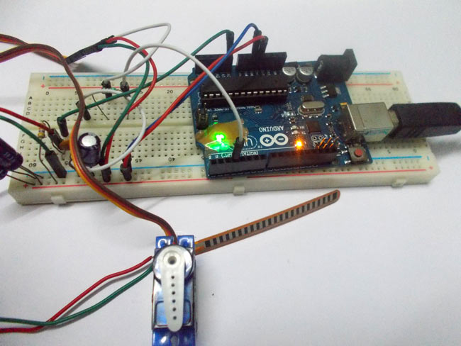
Servo motors are available at different shapes and sizes. A servo motor will have mainly there wires, one is for positive voltage another is for ground and last one is for position setting. The RED wire is connected to power, Black wire is connected to ground and YELLOW wire is connected to signal.
A servo motor is a combination of DC motor, position control system, gears. The position of the shaft of the DC motor is adjusted by the control electronics in the servo, based on the duty ratio of the PWM signal the SIGNAL pin.
Simply speaking the control electronics adjust shaft position by controlling DC motor. This data regarding position of shaft is sent through the SIGNAL pin. The position data to the control should be sent in the form of PWM signal through the Signal pin of servo motor.
The frequency of PWM (Pulse Width Modulated) signal can vary based on type of servo motor. The important thing here is the DUTY RATIO of the PWM signal. Based on this DUTY RATION the control electronics adjust the shaft. For the shaft to be moved to 9o clock the TURN ON RATION must be 1/18.ie. 1 milli second of ‘ON time’ and 17 milli second of ‘OFF time’ in a 18 ms signal.
For the shaft to be moved to 12o clock the ON time of signal must be 1.5ms and OFF time should be 16.5ms. This ratio is decoded by control system in servo and it adjusts the position based on it.
This PWM in here is generated by using ARDUINO UNO. So for now we know that, we can control the servo motor shaft by varying the duty ratio of PWM signal generated by Arduino Uno. The UNO has a special function which enables us to provide the position of SERVO without troubling the PWM signal. However it is important to know the PWM duty ration – servo position relation. We will talk more about it in description.
Now let’s talk about FLEX SENSOR. To interface a FLEX sensor to ARDUINO UNO, we are going use 8 bit ADC (Analog to Digital Conversion) feature to do the job. A FLEX sensor is a transducer which changes its resistance when its shape is changed. A FLEX sensor is of 2.2 inches long or of finger length. It is shown in figure.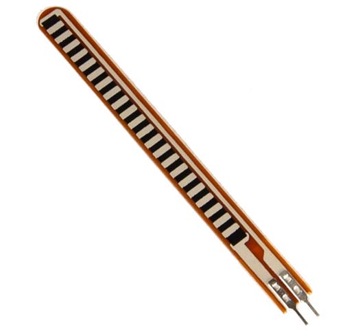
Flex sensor is a transducer which changes its resistance when the linear surface is bent. Hence the name flex sensor. Simply speaking the sensor terminal resistance increases when it’s bent. This is shown in below figure.
This change in resistance can do no good unless we can read them. The controller at hand can only read the chances in voltage and nothing less, for this we are going to use voltage divider circuit, with that we can derive the resistance change as voltage change.
Voltage divider is a resistive circuit and is shown in figure. In this resistive network we have one constant resistance and other variable resistance. As shown in figure, R1 here is a constant resistance and R2 is FLEX sensor which acts as a resistance.
The midpoint of branch is taken to measurement. With R2 change, we have change at Vout. So with this we have a voltage which changes with weight.
Now important thing to note here is, the input taken by the controller for ADC conversion is as low as 50µAmp. This loading effect of resistance based voltage divider is important as the current drawn from Vout of voltage divider increases the error percentage increases, for now we need not worry about loading effect.
FLEX SENSOR when bent its resistance changes. With this transducer connected to a voltage divider circuit, we will have a changing voltage with FLEX on transducer. This variable voltage is FED to one of ADC channels, we will have a digital value relating to FLEX.
We will match this digital value to servo position, with this we will have servo control by flex.
Read More: Servo Motor Control by Flex Sensor
- What is the primary function of the servo motor in this project?
The servo motor shaft position is determined by the flex or bent deviation of the FLEX sensor. - How are the wires connected on a standard servo motor?
The RED wire connects to power, the BLACK wire to ground, and the YELLOW wire to the signal pin. - What type of signal does the Arduino Uno send to the servo motor?
The Arduino generates a PWM signal where the duty ratio adjusts the shaft position. - What specific ON time is required for the shaft to move to the 12 o'clock position?
The ON time must be 1.5ms with an OFF time of 16.5ms in an 18ms signal. - How does a Flex sensor change its electrical properties when bent?
The terminal resistance of the Flex sensor increases when it is bent. - Why is a voltage divider circuit necessary for the Flex sensor?
A voltage divider converts the changing resistance of the sensor into a measurable changing voltage. - Which feature of the Arduino Uno is used to read the Flex sensor data?
The 8 bit ADC (Analog to Digital Conversion) feature is used to interface the sensor. - Can servo motors be used for high-speed applications?
No, servo motors are proposed for low speed, medium torque, and accurate position applications.