Summary of Servo Feedback Hack (free)
This article details a cost-effective hack to add shaft position feedback to hobby servos by tapping into the internal potentiometer. Using basic tools like a soldering iron and multimeter, users can modify a servo (specifically the Hitec HS-322) to report its current angle via an Arduino. The process involves disassembling the servo, locating the wiper wire on the PCB, and soldering an external feedback wire. This modification allows for restart stability and enables advanced features like collision detection and haptic control.
Parts used in the Servo Feedback Hack:
- Arduino or other microcontroller
- Hobby servo (Featured: HITEC-322HD)
- Stranded wire (smaller than 20 gauge, e.g., 24g)
- Set of small screwdrivers
- Wire snips
- Wire strippers
- Soldering iron and solder
- Multimeter
- Resistors (1K, 4.7K, 3.3K, 2.2K, or similar)
- Small knife
This Instructable brought to you by the kind folks a Rachel’s Electronics
Visit www.rachelselectronics.com for cool electronics kits and breadouts!
This hobby servo hack will add shaft position feedback by tapping into the servo’s own internal potentiometer. The only parts that need are wire and a little bit of solder, making this hack practically free. Common electronics workshop tools are required, so if you’re minimally set-up and already have a servo, it should take you less than an hour to make the modification and run the test code.
I thought of this after building projects with servos and getting frustrated by the fact that after restart, the servo would zoom around if it wasn’t already at the first coded position. There are code samples below (Arduino) that map the servo’s range to the feedback with minimal offset.
As with any hack, you assume some risk of wrecking your servo motor, so use a cheap one!
Discussion topics include: Collision Detection. Gestural Keyframing. Software Increase of Torque. Haptic Control…. (uuh, fill in the blank folks!)
Step 1: Servo Surgery
The Hitec servo comes apart very easily. Simply remove the four screws (bottom of servo, where wires come out). This also makes it possible to access the gear train (top of the servo, where the shaft comes out), so make sure that you keep the rest of the housing together. If you have a loose housing, put some tape over the seam to hold it together while you make this modification. Lift off the cover plate, and you will expose the bottom of the control PCB. We have to dig deeper to find out which one of these solder blobs is connected to the wiper pin of the internal potentiometer. Use a small flat screwdriver to pry up the PCB. start in one of the corners opposite from the cables. the PCB is soldered directly to the motor pins, and the whole unit should slide out smoothly. Careful not to let the gear housing open up! Now you can see that the yellow wire is the one that goes to the wiper, and also locate the solder blob that we will be attaching out sensor wire to.
Step 2: Finding Voltage
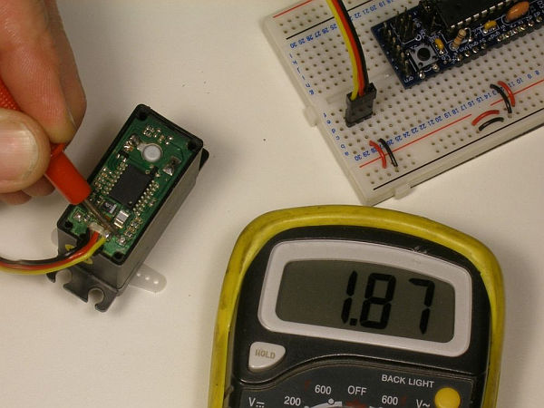
Looking for the potentiometer wiper wire.
On the HS-322 this is the little yellow wire that dives deep into the housing. Turn your servo all the way to one direction, and plug the servo cable into power and ground. Test voltage at the solder blob indicated in the previous step with your multimeter. Then turn the servo all the way in the other direction. I got 0.40V and 1.87V at each extreme. I hacked two Hitec servos for this instructable. The other one reads 0.41V and 1.86V. While you’re probing around there with your meter, notice how close some of the surface mount parts are. In the next step, we will be soldering right next to them.
Step 3: Soldering The Feedback Wire

Soldering is fun and you will get better at it the more you do it!
I have a Weller WP25. It’s a workhorse. The dial got pulled off and eaten by the dog at some point, but I can still approximate the settings. I set the temperature just below the mid point for most of my re-work. (~550 degrees F). The tip I’m using is catalog # TP-7, if you’re shopping. You can do this maneuver with a blunter iron, but please watch out for the surface-mount (SMT) parts adjacent.
The trick to making this go smoothly is to pre-tin the end of wire that you will add to the circuit. First strip about 1/2″ of insulation from the wire, twist up the strands, and then add solder. There is already a pretty big blob on the PCB, so we don’t need much on the wire, but a good coating will help the connection flow. Next, trim the tinned end down to a length that fits to the solder blob in question.
With the exposed bit wire already tinned it becomes a pretty straight-forward “heat-em-up”. Hold the tinned and trimmed end of the wire over the solder blob. if it sticks out to far past, you may need to trim some more (see last photo this step). When you’re satisfied with the length, place the wire on top of the solder blob, and put the iron on top of it. You’re kind of sadwiching the wire end between the iron and the blob. Now is the time to cultivate patience. All you have to do is wait for the heat from the iron to melt the solder that’s in the wire. That will transmit heat to the solder blob, melting it, and then the wire will mush into the blob. When that happens, remove the iron and keep holding the wire in place while it cools. You can blow on it gently if you like.
In the unlikely and potentially disastrous event that you ‘bridge’ the solder blob and it’s closest neighbor, I have some tips for pulling your servo back from the brink. First, let the parts cool. Then take a close look at the are. You should see clearly a patch of green PCB between the blob and the SMT part. That’s a resistor, by the way and if you have a magnifying glass you can read the three digit value (first two numbers are the value, third adds the zeros). Take a close look at the last picture below. Inside the yellow square, and just below the solder blob of interest, the PCB has some green patterns in it. The light colored green patches are copper traces (or fields, or pads) and the dark colored lines are non-conducting spaces between traces. The pad that the blob is on is isolated from the field around it, but connected to the left end of the SMT resistor. Can you see that? Good. If you’ve bridged the blob to the left end of the resistor only, then your good as done. There is already a connection there. The right side is a problem. You can try to wick or suck the solder away, and if there is a lot, you may need to try, but be aware that you don’t want to wick-up or suck-up the SMT part! If there is just a little bridge, then you can cut it with your knife. The solder is mostly tin and some other stuff. Very easy to cut with a little steel blade. When you cut, don’t expect to go straight through the middle of a blob. It’s more like carving or whittleing. Care should be taken not to cut through a trace or other PCB connection. And watch out for those wires.
If you can’t see the resistor on the PCB, the next best place is stuck under surface tension to the tip of your soldering iron. Roasted.
Major Components in Project
Parts and tools needed to complete this mod:
> Arduino (or other microcontroller) and it’s attendant parts.
> Hobby servo (Featured: HITEC-322HD)
> Stranded wire (Should be smaller than 20 gauge. I use 24g)
> Set of small screwdrivers.
> Wire snips
> Wire strippers
> Soldering iron and solder.
> Multimeter.
> A few resistors (1K, 4.7K, 3.3K, 2.2K, or similar)
> Small knife
For more detail: Servo Feedback Hack (free)
- How do I access the internal components of the servo?
Remove the four screws at the bottom where wires come out and pry up the PCB with a small flat screwdriver. - Which wire connects to the wiper of the internal potentiometer?
The yellow wire is the one that goes to the wiper pin. - What voltage range did the author observe at the extremes?
The author measured approximately 0.40V to 1.87V depending on the specific servo unit tested. - Can I use a blunter iron for this project?
Yes, but you must watch out for surface-mount parts adjacent to the work area. - How should I prepare the wire before soldering?
Strip about 1/2 inch of insulation, twist the strands, and pre-tin the end with solder. - What is the best way to fix a solder bridge between the blob and a neighbor?
You can try to wick the excess away, cut it with a steel blade, or ensure it only bridges to the resistor side which may already be connected. - Does this modification require expensive parts?
No, the only parts needed are wire and a little bit of solder, making it practically free. - What risk is associated with this project?
You assume the risk of wrecking your servo motor, so it is recommended to use a cheap one.