
Summary of Serial Call and Response with ASCII-encoded output using Arduino
This article demonstrates an Arduino project using ASCII-based string communication with a computer via a handshaking method. The sketch sends initial data and repeats sensor readings (three values) upon receiving a response, utilizing the Serial Monitor or software like Processing. This approach allows sending values larger than 255 and ensures human-readable output compared to binary transmission.
Parts used in the Serial Call and Response in ASCII Project:
- Arduino Board
- (2) analog sensors (potentiometer, photocell, FSR, etc.)
- (1) momentary switch/button
- (3) 10K ohm resistors
- breadboard
- hook-up wire
This example demonstrates string-based communication from the Arduino board to the computer using a call-and-response (handshaking) method.
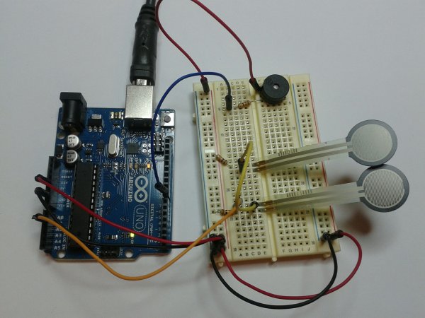
The sketch sends an ASCII string on startup and repeats that until it gets a serial response from the computer. Then it sends three sensor values as ASCII-encoded numbers, separated by commas and terminated by a linefeed and carriage return, and waits for another response from the computer.
You can use the Arduino serial monitor to view the sent data, or it can be read by Processing (see code below), Flash, PD, Max/MSP (see example below), etc. The examples below split the incoming string on the commas and convert the string into numbers again.
Compare this to the Serial call and response example. They are similar, in that both use a handshaking method, but this one encodes the sensor readings as strings, while the other sends them as binary values. While sending as ASCII-encoded strings takes more bytes, it means you can easily send values larger than 255 for each sensor reading. It’s also easier to read in a serial terminal program.
Software Required
Circuit
Connect analog sensors to analog input pin 0 and 1 with 10Kohm resistors used as voltage dividers. Connect a pushbutton or switch connected to digital I/O pin 2 with a 10Kohm resistor as a reference to ground.
image developed using Fritzing. For more circuit examples, see the Fritzing project page
Schematic

Code
Serial Call and Response in ASCII
Language: Wiring/ArduinoThis program sends an ASCII A (byte of value 65) on startup
and repeats that until it gets some data in.
Then it waits for a byte in the serial port, and
sends three ASCII-encoded, comma-separated sensor values,
truncated by a linefeed and carriage return,
whenever it gets a byte in.
Thanks to Greg Shakar and Scott Fitzgerald for the improvements
The circuit:
* potentiometers attached to analog inputs 0 and 1
* pushbutton attached to digital I/O 2
Created 26 Sept. 2005
by Tom Igoe
modified 24 Apr 2012
by Tom Igoe and Scott Fitzgerald
This example code is in the public domain.
http://www.arduino.cc/en/Tutorial/SerialCallResponseASCII
*/
Hardware Required
- Arduino Board
- (2) analog sensors (potentiometer, photocell, FSR, etc.)
- (1) momentary switch/button
- (3) 10K ohm resistors
- breadboard
- hook-up wire
For more detail: Serial Call and Response with ASCII-encoded output using Arduino
- How does the Arduino communicate with the computer?
The sketch uses a call-and-response handshaking method where it sends an ASCII string on startup and waits for a serial response before sending sensor data. - What format are the sensor values sent in?
Sensor values are sent as three ASCII-encoded numbers separated by commas and terminated by a linefeed and carriage return. - Can this method send values larger than 255?
Yes, encoding sensor readings as strings allows you to easily send values larger than 255 for each sensor reading. - What software is required to read the data besides the Serial Monitor?
You can use Processing or Max/MSP version 5 to read the incoming data and convert the string into numbers. - How many 10Kohm resistors are needed for the circuit?
The circuit requires three 10Kohm resistors used as voltage dividers for the sensors and as a reference to ground for the pushbutton. - Where should the analog sensors be connected?
Analog sensors should be connected to analog input pins 0 and 1. - Which digital pin is used for the pushbutton?
A pushbutton or switch is connected to digital I/O pin 2. - What is the main advantage of using ASCII strings over binary values?
Using ASCII-encoded strings makes the data easier to read in a serial terminal program compared to binary values.
