In a couple of weeks, some students will visit my lab (Craft Tech Lab) to learn more about wearable technologies. I wanted to build a quick and simple application of a sensor and vibration motors for them to play around with and rough up. While this project could be made into a wearable mask, due to germs I’ll be having the students point the papercraft mask in different directions by hand with the vibration headband being detached from the mask. Also, because I expect them to destroy the mask, this project is breadboarded so that I can create another mask and move/repurpose the components easily.
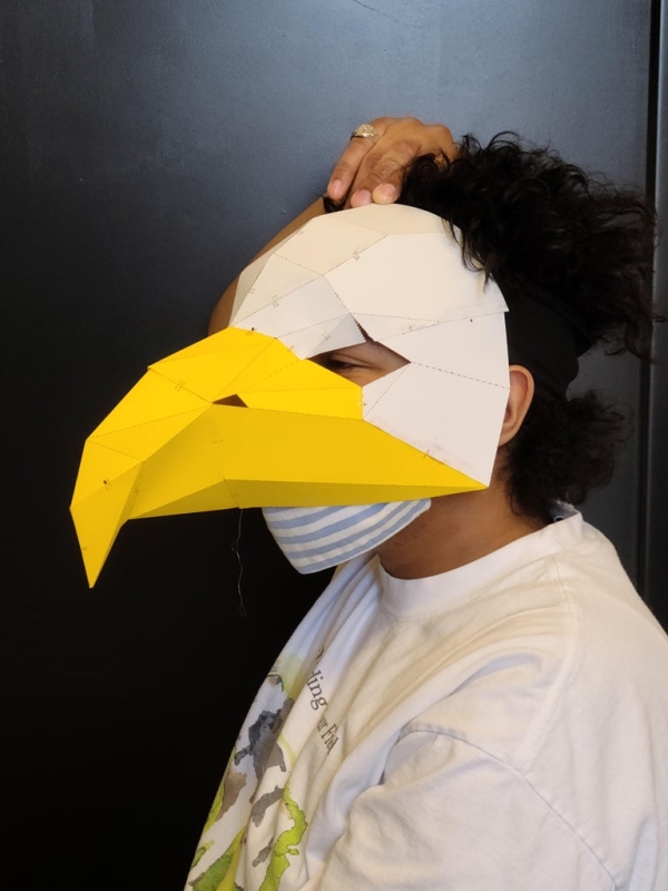
The mask senses direction through a 3-axis magnetic electronic compass sensor (HMC5883L) that is hidden in the beak. The sensor interfaces with an Arduino Nano that acuates vibration motors that are hidden in a headband (Figure 3), and the headband is worn such that the middle motor is touching the back of the user’s head and the two side motors are resting near the temples. When the user is facing away from north, the vibration motors will indicate which direction they need to turn the mask for it to be facing north again.
This project was developed in the Craft Tech Lab and ATLAS Institute at The University of Colorado, Boulder.
If you have any questions, want to keep up with my work, or just toss around ideas, please do so on my Twitter: @4Eyes6Senses. Thanks!
Step 1: Materials
1x Paper Craft Mask (mine is from Etsy seller PaperAmazeDigital)
3x ERM vibration motors
1x 3-axis magnetic electronic compass sensor (HMC5883L)
1x Arduino Nano
1x Headband
1x Mini breadboard
Silicone Wire
Heat shrink tubing
Solder & soldering iron
Hot glue & hot glue gun
Drill
Step 2: Fabricate the Paper Craft Mask
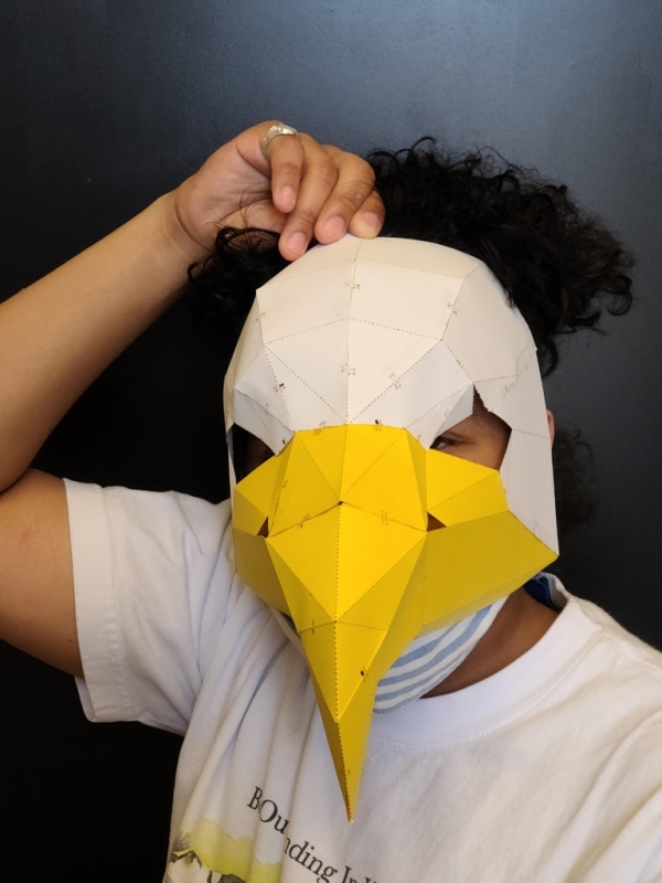
For my mask, I purchased this template from the Etsy seller PaperAmazeDigital (it took about an hour to cut, attach, and glue the mask together). Because the paper craft template is not my own creation and is for sale, I will not share it publicly or privately, if you want to recreate the mask that’s shown in this project please support the creator!
An alternative is to find a free template online or find instructions on how to create a bird mask using alternative materials, like what user speltbaker has done.
Step 3: Prepare the Vibration Motors
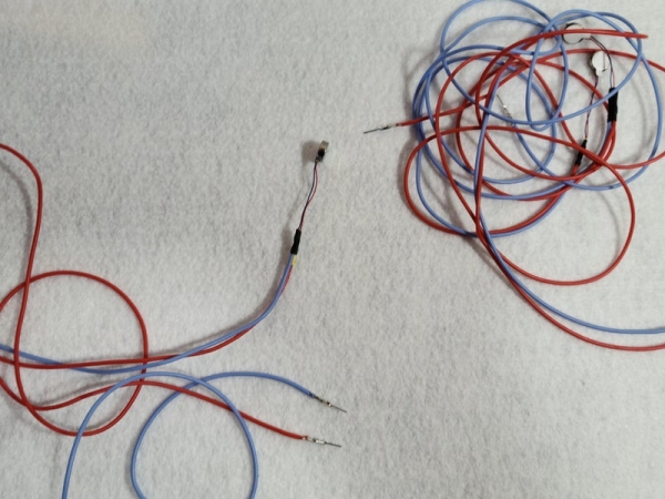
The headband uses three vibration motors (Figure 1) to indicate the direction of north. Before adding the motors to our project, we need to extend the red and blue wires:
– Solder silicon wire to the wires on the vibration motors (Figure 2) – I used around 1.5 feet for each wire. Be gentle while soldering as it is easy to break the wires that are attached to the vibration motors.
– After each motor has been extended, we need to insulate the exposed wires. Slide some heat shrink tubing over one of the soldered wires (Figure 3).
– Then slide another heat shrink tube over both wires (Figure 4).
– Repeat until all three motors look like figure 5.
– Attach male Dupont connectors to each wire (Figure 6).
Step 4: Attach Vibration Motors to the Headband
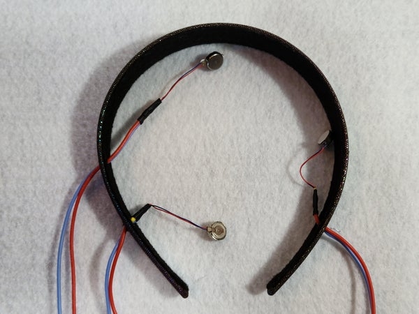
We will now add the vibration motors to the headband. The vibration motors will be oriented so that two will sit on the side of the head and one will rest against the back of the head.
– Drill three holes into the headband (Figure 1).
– Thread the vibration motors through the holes on the inside of the headband (Figure 2).
– Use hot glue to secure the vibration motors to the headband.
Step 5: Connect Sensors and Vibration Motors to Nano
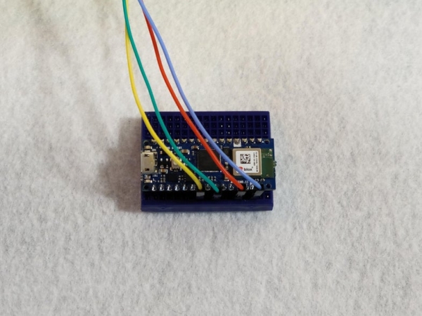
– Connect the compass sensor to the Nano’s 5v, GND, SCL, and SDA pin (Figure 1 & 2):
VCC O —- O +5v
GND O —- O GND
SCL O —- O A5
SDA O —- O A4
DRDY O —- X NOT CONNECTED
– Connect the vibration motors to the following pins (orientation is for when the headband is worn): Right motor blue wire to GND, Red wire to D12. Middle motor blue wire to GND, red wire to D6. Left motor blue wire to GND, red wire to D3.
– At this step your breadboard should look like figure 3.
Step 6: Upload Code to Nano
Before you can run the code on a Nano you need to add the QMC5883L library to the Arduino IDE.
The logic to read the mask’s direction and actuate the vibration motors is straightforward:
When facing south, actuate the back vibration motor to indicate that north is in the opposite direction.
When facing east, actuate the left vibration motor to indicate that the mask needs to be turned left to face north.
When facing west, actuate the right vibration motor to indicate that the mask needs to be turned right to face north.
Step 7: Glue Sensor and Breadboard to Mask
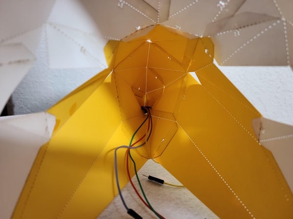
For my mask, I hot glued the sensor and breadboard to the mask, like shown in figures 1 & 2.
Source: Sense Direction Like a Bird: Sensory Extension Mask