Summary of Self-Watering Smart Pot Using NodeMCU
This article details the construction of a Self-Watering Smart Pot using an ESP8266 NodeMCU. The device automates plant watering, monitors soil moisture, temperature, and humidity via a mobile app, and prevents overwatering. It utilizes capacitive sensors for water detection and a DHT11 sensor for environmental data, with manual control options available through the Blynk application.
Parts used in the Self-Watering Smart Pot:
- ESP8266 NodeMCU
- Capacitive soil moisture sensor
- DHT11 sensor module
- L293d motor driver or relay
- 5v mini water pump
- 1 meter small 1cm hose
- 7.4 volt battery (or 9v/6v)
- Female header pins
- 1N4007 diodes
- Common PCB
- Wires
let’s build a self-watering (also we can monitor the temperature, humidity, soil moisture )smart pot using nodemcu

Description
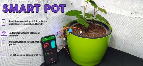
Self-Watering Smart Pot Using NodeMCU
Hello there,
Sometimes when we go out of our home for a few days. In this case, we cant give water to our favourite plants or we are busy with other works at that time we always forget to give water to our plants, most of the time we nearly forget about our plants in the mentioned cases It’s hard to keep our plants alive. Because most of the indoor plants require regular watering. Here I came with a simple solution. This is just awesome for lazy and busy people like me.
My solution is a Self-Watering Smart Pot. Any normal pot can be converted into a smart pot. With smart pot, we can make our plants healthy and happy
First, let’s see the features.
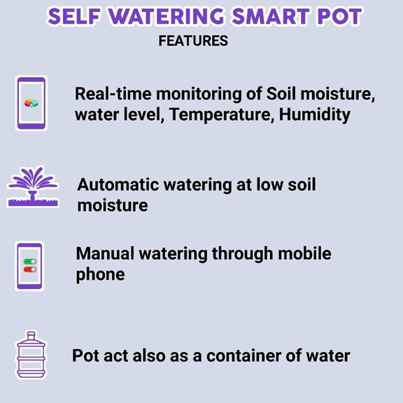
- It will automatically give water when the plant needs water
- It will show the water percentage in the soil through the app (from anywhere under the sun where the internet is available)
- Also, it will show the temperature and humidity of the plant surroundings
- The pot also acts as a container for water. This makes some sort of clean (we don’t need to place any bulky water container near )
- The sensor will detect the water level and shows in percentage.
- We can manually give water to plants through the app.
- There is no chance of overwatering.
Working of the Self Watering Smart Pot
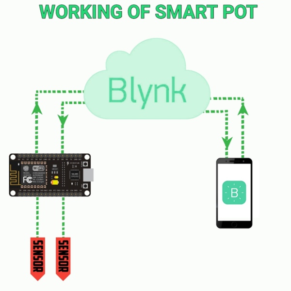
In an automatic plant watering system or the smart pot. we are using an esp microcontroller to control and sense everything. To measure the moisture in the soil and water level we are using a capacitive soil moisture sensor. with the help of the DHT11 sensor, we can measure the temperature and humidity. After reading these values we will send these values to the Blynk server (that’s why we are using esp microcontroller.) so that we can monitor the values using a mobile app. we can set the moisture level of the soil to turn on and off the attached water pump. We can also manually control this pump through the mobile application. So this is basically how a smart pot works.
Components Required for Making the Self Watering Smart Pot
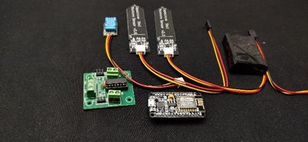
- ESP8266 NodeMCU*1
- Capacitive soil moisture sensor*2
- DHT11 sensor module*1
- L293d motor driver/ relay*1
- 5v mini water pump*1
- 1 meter small 1cm hose*1
- 7.4 volt battery(9v or 6v)
- Female header pins
- 1N4007 diodes*2
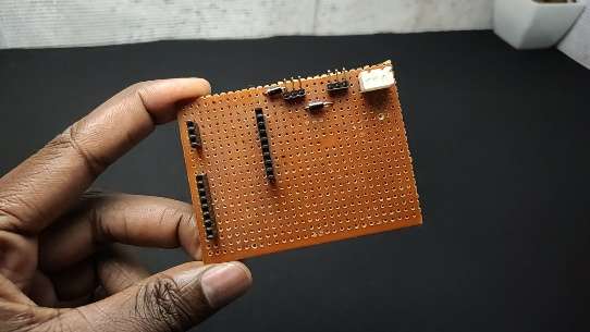
- Common PCB
- Wires
Esp8266 NodeMCU
we can use any microcontroller to build an automatic irrigation system. But to convert that to smart of course we need an internet connection, that is why I am going with the nodemcu. We can send or receive data using nodemcu. It has enough digital pins for our application.
The capacitive soil moisture sensor
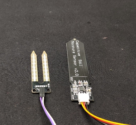
The job of a soil moisture sensor is to detect the water content of the soil. When it comes to this category of sensor we have two options that are Capacitive Soil Moisture Sensor and resistive moisture sensor. As the name indicates a Capacitive soil moisture sensor is based on capacitance changes. Compared with resistive sensors, capacitive sensors do not require direct exposure of the metal electrodes, which can significantly reduce the corrosion of the electrodes.
A capacitive moisture sensor works by measuring the changes in capacitance caused by the changes in the dielectric. As all, we know capacitance is proportional to the dielectric medium. The capacitance of the sensor is measured using a NE555 based circuit that produces a voltage proportional to the capacitance. The sensor has 3 pins VCC, GND and OUT. The output of a capacitive moisture sensor is an analogue value.
Also, we can use capacitive moisture as a water level sensor.
DHT11
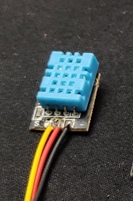
The DHT11 is a commonly used temperature and humidity sensor. The sensor comes with a dedicated NTC to measure temperature the output of the DHT sensor comes as serial data of temperature and humidity. The sensor is much accurate than other sensors and easy to interface with microcontrollers using the DHT library. The sensor can measure temperature from 0°C to 50°C and humidity from 20% to 90% with an accuracy of ±1°C and ±1%. So this is perfect for our application
Motor driver/ relay
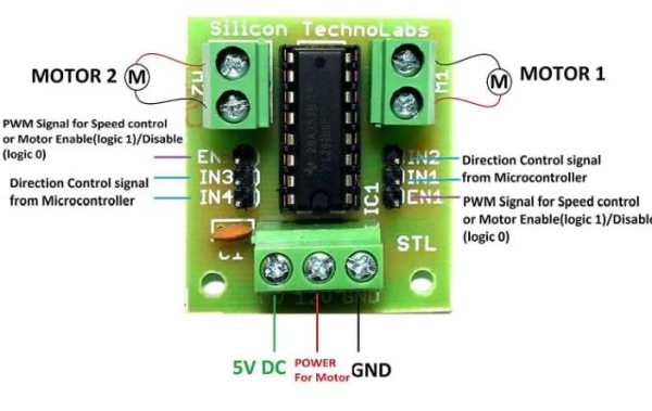
We can’t directly connect the motor pump to the microcontroller because pumps will draw more current so leading to the destruction of the microcontroller. So to control the pump, I used the L293D IC module, I choose this IC because to decrease the size. And this IC is good for controlling small motors. You can also use a relay. This module is designed for controlling 2 motors. We need only one side.
Circuit Diagram of Self Watering Smart Pot
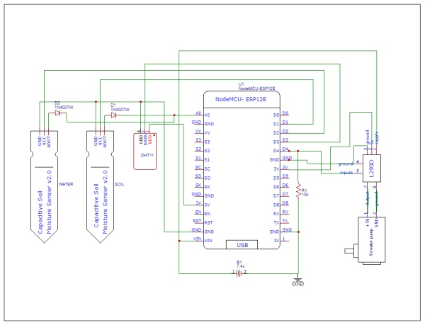
In this section, I will explain all the details circuit diagram. The Nodemcu is the brain of this smart pot project.it reads the values of moisture sensors and DHT module then it sends that’s values to the Blynk server through a wifi connection. also, It controls the pump according to the moisture in the soil or with the app commands.
Unlike other development boards like Arduino, blue pill nodemcu has only one analogue pin. But we have two analogue moisture sensors! So how to read two analogue values using one analogue pin.? In the coming lines, I am explaining how to read multiple analogue values using only one pin.
in this circuit diagram, you can see I connected positive terminals of moisture sensors to digital pins 1 and 2 so we can turn off and on each sensor by turning on and off the digital pins. That is if the d1 is on that means sensor one is on. I connected a diode on the outputs of each sensor and the other side of the diode I connected to the analogue pin. Here comes the trick first we turn D1 (that is sensor 1) at the same time we read the analogue value. So we get the analogue value of the first sensor. Next, we turn off D1 and turn on the D2 and read the analogue value so we will get the analogue value of the second sensor. here diode is for isolation between the sensors. check the coding part too for better understanding.
I connected the DHT sensor to digital pin 3 and the motor driver/relay to D4. A 10k resistor is used to pull down the motor pin. This L293D motor driver module has three power pins ground, supply and a 5v. So I connected ground to ground supply to the positive side of the battery and 5v to the 3.3v pin of nodemcu. Also, remember to connect the enable to a 3.3v pin.
To power the circuit, I am using an external Battery. You can use any 6-12v battery(i recommend using an AC adapter for this). The battery is connected to the Vin and ground pins of Nodemcu and we can also connect the motor driver supply to this battery.
Source: Self-Watering Smart Pot Using NodeMCU
- How does the system prevent overwatering?
The system prevents overwatering by automatically turning off the water pump when the soil reaches the set moisture level. - Can I manually water the plant using this project?
Yes, you can manually give water to plants through the mobile application interface. - What type of sensor is used to measure soil moisture?
A capacitive soil moisture sensor is used because it reduces electrode corrosion compared to resistive sensors. - Why are two diodes included in the circuit?
The diodes provide isolation between the two moisture sensors so their outputs do not interfere with each other. - How does the system handle two analogue sensors with one pin?
The microcontroller turns on digital pins sequentially to activate each sensor individually before reading the shared analogue pin. - What component controls the water pump?
An L293D motor driver IC or a relay is used to control the pump since the microcontroller cannot handle the high current directly. - Which app is used to monitor the plant data?
The Blynk server and mobile app are used to display water percentage, temperature, and humidity values. - What is the recommended power source for the circuit?
An external battery between 6-12 volts is recommended, though an AC adapter is suggested for stability.