Summary of Self-Stabilizing Utensil for Parkinson’s Disease Patients: A Self-Stabilizing Parkinson’s Eating Aid
Summary: The project developed a Self-Stabilizing Parkinson’s Eating Aid: an auto-configuring utensil stabilization system using an MPU6050 accelerometer, two servos, Arduino Nano, and 3D-printed ball-and-socket joints to reduce tremor-related spillage and improve independent eating for Parkinson’s patients. Design steps included planning, circuit diagrams, Fritzing and hand drawings, CAD, simulation, structural testing, 3D printing, assembly, user trials, and iterative improvements.
Parts used in the Self-Stabilizing Parkinson’s Eating Aid:
- Arduino Nano
- MPU6050 accelerometer
- Two servo motors
- Breadboard
- Jumper wires
- Solder and soldering tools
- 3D-printed ball-and-socket joint pieces (Piece 1 and Piece 2)
- Fusion 360 CAD files (for printing)
- PPS or PLA 3D printing material
- Acrylic pieces for servo enclosure
- Battery pack
- Wrist strap
- Plastic spoon (interchangeable utensil end)
- Superglue
- Acrylic box/enclosure
- USB cable or power supply option (discussed as alternative)
The core objective of the project is to develop a Self-Stabilizing Parkinson’s Eating Aid—an auto-configuring device designed to prevent food spillage. The primary use case focuses on patients with Parkinson’s Disease (PD). The device’s function is to mitigate the unwanted tremors that many PD patients experience, providing a viable solution to a challenging situation faced by patients. This directly benefits patients by enhancing their ability to eat independently and reducing mess.
Parkinson’s disease (PD) is a rapidly progressive neurological disorder that greatly affects a person’s everyday functioning in the form of symptoms such as tremor and nervous system degeneration. As a consequence, this project will help address these everyday impairments with the introduction of a bioengineered system that will allow PD patients to eat independently and comfortably, thereby improving the quality of life living with PD.
The initial step in developing the device was detailed project planning. The goal was to create a clear roadmap for successful semester completion. Key planning tools included a timeline, proposal with scope, BOM, sketches, and a cardboard prototype. These helped visualize the full scope and define the sequence of tasks. Early planning ensured the smooth integration of all components. This structured approach supported the development of an effective assistive device for PD patients.
The following documents can be found here:
The main purpose of this project was to create a device inspired by an online video. The video offered helpful resources—ready-made code and circuit diagrams—that were directly applied in the project. This technique was useful for the creator in particular because they had little experience archiving Arduino coding and circuit building. A clear example enabled them to tackle a challenging technical project, use the video as a learning tool and project guide, and ultimately produce a working product.
The link for the video can be found here:
Self-Stabilizing Spoon For Parkinson’s Sufferers | Arduino Project
The goal of this stage was to turn ideas from the videos into actual circuit designs. The creator made two diagrams—one by hand and another using Fritzing software. These visuals applied the learned concepts and served as blueprints for building the circuit. They help ensure accuracy and ease troubleshooting. This is especially useful for beginners, providing a clear view of how components connect.
Hand-Drawn Circuit Design:

Fritzing Circuit Design:

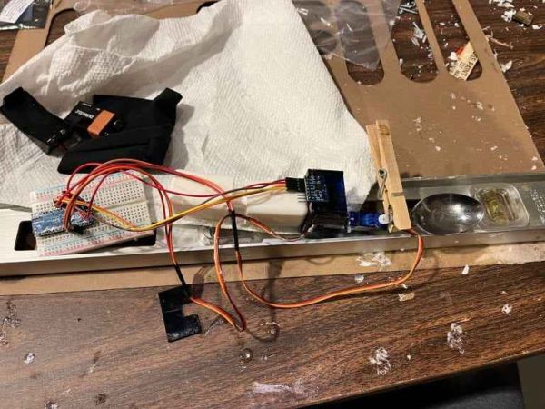
This section transitioned the project’s ongoing process of design to a physical construction phase of assembly with circuit testing and soldering. The MPU 6050 accelerometer played a key role in providing the sensor capabilities needed to detect movement. The MPU quickly and reliably responds to changes in inertia, so movement tracking and stabilization are important aspects of its ability to help support the device.
Soldered Arduino Nano to Breadboard:

3D Printing for Enhanced Mobility
This phase focused on designing and fabricating 3D-printed ball-and-socket joints using Fusion 360. The design process involved researching diameter adjustments to achieve a secure fit while allowing smooth rotation. The initial model combined both the ball and socket into a single piece for testing. These joints aim to increase the range of motion for individuals with Parkinson’s disease when using a utensil, offering a practical mechanical solution to improve comfort and usability for those with motor control challenges.
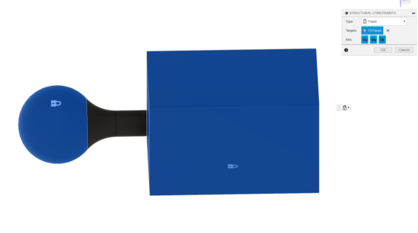
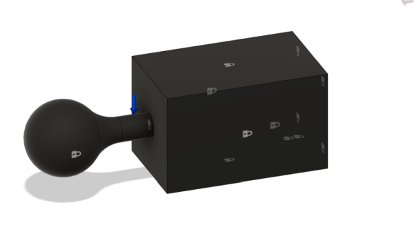
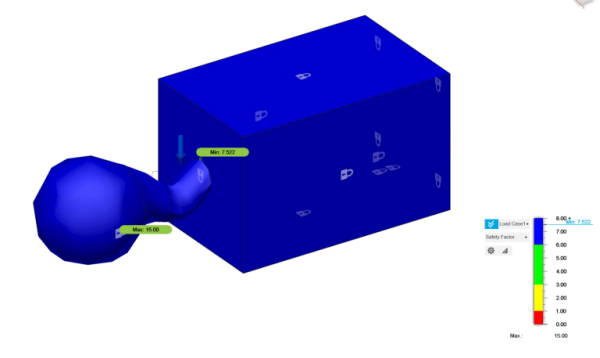
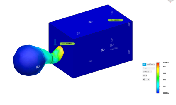
The objective of this stage was to assess the structural strength of the 3D-printed ball-and-socket joint, focusing on the thinness of the neck to maximize flexibility. Fusion 360 simulated the design against a 225N grip force, and the team conducted structural testing to evaluate how well the arm withstood this pressure. Although they used PPS plastic instead of PLA, the analysis offered valuable insight into the joint’s reliability, helping ensure the device remains safe and effective for patients with Parkinson’s disease.
The CAD file and simulation results validate the joint’s design, confirming durability and reducing flaws before production for improved patient use.

First Ball-and-Socket Joint Piece
Simulation:
Safety Factor (left) Stress (right):
Structural Testing Phase
The focus was on validating the structural integrity of the ball-and-socket joint before moving to physical prototyping. Simulation results confirmed the neck’s strength, showing a high safety factor of 7.522 under a 225N force and a low tension value of 9.16 MPa, well within safe limits. After this validation, the team 3D-printed the first design and carried out post-processing, including removing supports and testing for proper fit and smooth movement. The joint performed well with minimal sanding, resulting in a functional, reliable component that meets the design goals. This success supports improved range of motion for Parkinson’s patients and confirms the 3D-printed solution’s feasibility.
Successful Ball-and-Socket Joint
The goal was to fix early design flaws in the 3D-printed ball-and-socket joint. Issues included both parts containing a ball and socket, and sharp, uncomfortable corners. After adjustments in the CAD, there were two new files that came out of it, called “Piece 1” and “Piece 2.” The redesign aimed to improve joint ergonomics and enhance usability for the intended application. Additionally, the redesign made it more comfortable and practical for Parkinson’s patients.
Updated Ball-and-Socket Joints Pieces 1 & 2
The goal of this phase was to assemble the electronic circuit and integrate the software. Using a breadboard and jumper wires allowed for quick, flexible construction. Once all components arrived, the circuit was assembled and programmed. Troubleshooting led to successful operation. This established a working core for the assistive utensil’s function.
Stabilized Utensil for Parkinson’s
The system stabilizes the utensil by responding to hand tremors caused by Parkinson’s disease. This system uses two servo motors that respond and adjust in real-time through the MPU 6050 accelerometer coordinates. One servo motor adjusts to compensate for movement in the XY plane, and one serves the XZ plane. The coordination is determined by code calculations. The circuit takes into account the inadvertent movement, which keeps food stable in the utensil. This ultimately aids with independent eating and minimizes spillage for patients with Parkinson’s disease.
The team housed two servo motors in an enclosure and connected them with a ball-and-socket joint. Initial acrylic prototypes limited the top servo’s motion, so they shortened the box to sit just below the bottom servo’s horn. Improved motor movement and reduced the box size for a more compact, functional design.
The basic purpose of this final stage was the complete physical assembly of all integrated components of the assistive utensil. This involved using superglue to securely fasten:
- All acrylic pieces form the servo enclosure.
- The two servo motors are connected.
- Assemble the servo motors into the acrylic box.
- The underside of the acrylic box is connected to the 3D-printed ball-and-socket joint.
- The battery pack is attached to the outside of the wrist strap.
The primary goal was to assemble all previously designed and tested parts into a cohesive unit. During this process, the team identified an important improvement area: the battery pack leads did not connect reliably to the breadboard. The non-solderless nature of these leads frequently resulted in disconnections due to minor movements. This highlights a practical challenge that, once addressed in future designs, will benefit the project by providing a more robust and reliable power supply, thereby improving the overall functionality and user experience of the assistive utensil for Parkinson’s patients.
Wrist Strap and Battery Pack

This segment focused on attaching a utensil to the servo motor for functional use in the Self-Stabilizing Parkinson’s Eating Aid. Superglue failed to hold a stainless steel spoon due to the torque from the ladle, revealing a material-adhesive mismatch. The team adapted the design to use a plastic spoon instead. This ensured reliable function and maintained usability for Parkinson’s patients.
Prototype with/ Stainless Steel Spoon Attached

Interchangeable Utensil Ends
The initial purpose was to make the ends of the utensil interchangeable from a spoon to a fork, using silicone casting or a 3D printed piece. The time constraints kept the team from moving ahead with this idea, so the team attached a spoon instead as a part of the utility of stabilizing the bowl. If this option were added, it would give flexibility depending on the type of food.
Grip Holders
This stage evaluated the product’s usability with four users. Each participant tested the stabilization feature and used the utensil to pick up a piece of paper. Their feedback revealed the device’s core functionality. These insights improve their practical application for Parkinson’s patients.
Their inclusion would improve handling comfort for users.
Both features remain promising areas for future development to enhance the usability and versatility of the assistive utensil.
This stage aimed to evaluate the product’s usability with four users. Each participant tested the stabilization feature and then used the utensil to pick up a piece of paper. This provided real-world feedback on core functionality. The insights gained help improve the practical application for Parkinson’s patients.
Basic Purpose of the Project
This project centers on a wired interactive device, likely for therapeutic or assistive use, being tested to assess its functionality and user-friendliness.
Uses and Applications
The device is designed for hands-on operation, which requires a steady power source (battery or USB), and minimal disturbance by exposed wiring, as the adjustable positioning creates the possibility for short circuits.
Benefit to Others
User testing revealed issues with battery stability and wire discomfort. Future improvements—like concealed wiring or USB power—will boost comfort, reliability, and everyday usability, especially for those relying on the device for assistance or therapy.
The project is a learning experience that combines knowledge from many disciplines while aiming to become a device that can has a medical impact with practical applications in the healthcare sector.
Read more: Self-Stabilizing Utensil for Parkinson’s Disease Patients: A Self-Stabilizing Parkinson’s Eating Aid
- What is the main purpose of the Self-Stabilizing Parkinson’s Eating Aid?
To stabilize a utensil and prevent food spillage for Parkinson’s patients by compensating for hand tremors using sensors and servos. - Which sensor is used to detect movement in the device?
The MPU6050 accelerometer is used to detect movement and changes in inertia. - How many servo motors does the system use and what do they do?
The system uses two servo motors: one to compensate movement in the XY plane and one for the XZ plane. - What materials were used for the ball-and-socket joints and how were they validated?
The joints were 3D-printed using materials such as PPS (and tested conceptually with PLA), validated through Fusion 360 simulation and structural testing showing a high safety factor. - How was the circuit design documented before assembly?
Circuit designs were made by hand and recreated in Fritzing software as visual blueprints for building the circuit. - What issue was found with the battery pack during assembly?
The battery pack leads did not connect reliably to the breadboard and frequently disconnected due to minor movements. - Why was a plastic spoon used instead of a stainless steel spoon?
Superglue failed to hold the stainless steel spoon because of torque, so a plastic spoon was used for reliable attachment. - What user testing was performed and what did it evaluate?
Four users tested the stabilization feature by using the utensil to pick up a piece of paper to evaluate core functionality and usability feedback. - What design tools were used for the CAD and simulation work?
Fusion 360 was used for CAD modeling and simulation of the ball-and-socket joint under load. - Can the utensil ends be made interchangeable?
The design considered interchangeable ends via silicone casting or 3D printing, but time constraints prevented implementing this feature; a spoon was attached instead.