Summary of RS-232
This tutorial shows how to connect an Arduino to a PC terminal using a MAX3323 single-channel RS-232 driver/receiver and SoftwareSerial. It covers wiring the chip and capacitors on a breadboard, making a DB9 serial cable, mapping Arduino TX/RX pins to the MAX3323, and uploading a simple echo-to-uppercase sketch for serial debugging.
Parts used in the MAX3323 RS-232 Arduino Project:
- Computer with a terminal program (HyperTerminal, RealTerm, Zterm, etc.)
- Serial-Breadboard cable (or DB9 connector and wires to make one)
- MAX3323 chip (or similar RS-232 driver/receiver)
- Four 1uF capacitors
- Solderless breadboard
- Hookup wire
- Arduino microcontroller module
- Light emitting diode (LED) - optional, for debugging
In this tutorial you will learn how to communicate with a computer using a MAX3323 single channel RS-232 driver/receiver and a software serial connection on the Arduino. A general purpose software serial tutorial can be found here.
Materials needed:
- Computer with a terminal program installed (ie. HyperTerminal or RealTerm on the PC, Zterm on Mac)
- Serial-Breadboard cable
- MAX3323 chip (or similar)
- 4 1uf capacitors
- Solderless breadboard
- Hookup wire
- Arduino Microcontroller Module
- Light emitting Diode (LED) – optional, for debugging
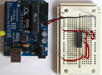
Prepare the breadboard
Insert the MAX3323 chip in the breadboard. Connect 5V power and ground from the breadboard to 5V power and ground from the microcontroller. Connect pin 15 on the MAX233 chip to ground and pins 16 and 14 – 11 to 5V. If you are using an LED connect it between pin 13 and ground.
+5v wires are red, GND wires are black
Connect a 1uF capacitor across pins 1 and 3, another across pins 4 and 5, another between pin 2 and ground, and the last between pin 6 and ground. If you are using polarized capacitors make sure the negative pins connect to the negative sides (pins 3 and 5 and ground).
+5v wires are red, GND wires are black
Determine which Arduino pins you want to use for your transmit (TX) and recieve (RX) lines. In this tutorial we will be using Arduino pin 6 for receiving and pin 7 for transmitting. Connect your TX pin (7) to MAX3323 pin 10 (T1IN). Connect your RX pin (6) to MAX3323 pin 9 (R1OUT).If you do not have one already, you need to make a cable to connect from the serial port (or USB-serial adapter) on your computer and the breadboard. To do this, pick up a female DB9 connector from radioshack. Pick three different colors of wire, one for TX, one for RX, and one for ground. Solder your TX wire to pin 2 of the DB9 connector, RX wire to pin 3 and Ground to pin 5.
Connect pins 1 and 6 to pin 4 and pin 7 to pin 8. Heatshrink the wire connections to avoid accidental shorts.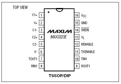
Program the Arduino
Now we will write the code to enable serial data communication. This program will simply wait for a character to arrive in the serial recieving port and then spit it back out in uppercase out the transmit port. This is a good general purpose serial debugging program and you should be able to extrapolate from this example to cover all your basic serial needs. Upload the following code into the Arduino microcontroller module:
For more detail: RS-232
- What is the purpose of the MAX3323 in this project?
The MAX3323 provides RS-232 level driving and receiving so the Arduino can communicate with a computer serial port. - Which Arduino pins are used for TX and RX in the tutorial?
Arduino pin 7 is used for transmit (TX) and pin 6 is used for receive (RX) in this tutorial. - How many capacitors are required and where do they go?
Four 1uF capacitors are required: across pins 1 and 3, across pins 4 and 5, between pin 2 and ground, and between pin 6 and ground. - How should I wire the DB9 connector for serial connection?
Solder TX wire to DB9 pin 2, RX wire to DB9 pin 3, and Ground to DB9 pin 5. - What power connections are needed for the MAX3323?
Connect 5V and ground from the breadboard to the microcontroller 5V and ground; connect MAX3323 pin 15 to ground and pins 16 and 14 through 11 to 5V; pins 16 and 14-11 to 5V as stated in the tutorial. - Do the capacitors have polarity considerations?
If using polarized capacitors, connect their negative leads to the negative sides (pins 3 and 5 and ground) as specified. - Can I use an LED in this setup?
Yes, an LED is optional for debugging and can be connected between pin 13 and ground on the MAX3323 as described. - What does the example Arduino program do?
The program waits for a character on the serial receiving port and sends it back out in uppercase on the transmit port for serial debugging.