
Summary of ROVER USES DIFFERENT KIND OF TRACKS
This article details James Bruton's construction of a self-balancing robot inspired by the 1940s Fordson Rotaped tractor. Unlike traditional tracked robots requiring multiple internal wheels, this design utilizes a single sprocket wheel per track with six long track sections. The project features 3D printed mechanical parts, bungee cords for track retention, and brushless motors controlled by O-Drive units. An Arduino Mega manages balance using PID tuning to counteract cogging effects, while an MPU6050 IMU provides position data via an Arduino Pro Mini.
Parts used in the Self-Balancing Rotaped Robot:
- Sprocket wheel (single per track)
- Long track sections (six per side)
- Bungee cord loop
- Brushless motors
- O-Drive controllers
- Arduino Mega
- Arduino Pro Mini
- MPU6050 IMU
- 3D printed mechanical parts
Tracked robots usually require at least two wheels inside to work properly. However, [James Bruton] discovered a curious tractor design from the 1940s, the Fordson Rotaped, which only uses a single sprocket wheel inside each track. Being [James], he built a self-balancing robot around the rotaped concept.
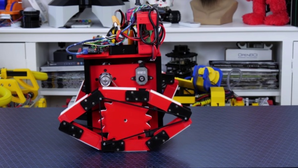
Instead of a lot of short track sections, the Rotaped uses six long sections of track, about the same length as the wheel’s diameter. To keep the track on the wheel, a series of chains or an oval frame is used on the inside of the track.
As is usual for [James]’ projects, most of the mechanical parts are 3D printed. To hold the tracks in place, he stretches a bungee cord loop around three points on each side of the track. To make things more interesting, he made the robot balanced on the tracks. This took a bit of PID tuning to get working without oscillations, since the wheels experience a slight cogging effect inside the tracks. The wheels are driven by a pair of brushless motors with O-Drive controllers. The balancing is handled by an Arduino Mega, which reads processed position values from an Arduino Pro Mini connected to an MPU6050 IMU.
This might be a viable alternative to conventional tracks for certain applications, and the reduced part count is certainly an advantage. Let us know in the comments if it spawns any ideas. [James] has previously built another tracked rover, which uses flexible 3D printed track sections. By far, the biggest 3D printed tracked vehicle we’ve seen was [Ivan Miranda]’s ridable tank.
Source: ROVER USES DIFFERENT KIND OF TRACKS
- How does the robot keep tracks on the wheel?
A series of chains or an oval frame is used on the inside of the track. - What holds the tracks in place mechanically?
A bungee cord loop is stretched around three points on each side of the track. - Which microcontroller handles the balancing logic?
An Arduino Mega reads processed position values to manage the balance. - What sensor provides position data for the system?
An MPU6050 IMU connected to an Arduino Pro Mini provides the data. - How are the wheels driven in this design?
The wheels are driven by a pair of brushless motors with O-Drive controllers. - What challenge did the builder face regarding motor performance?
The wheels experience a slight cogging effect inside the tracks that required PID tuning. - How many track sections are used compared to conventional designs?
The design uses six long sections instead of a lot of short track sections. - Are most mechanical parts made from metal or plastic?
Most of the mechanical parts are 3D printed.
