Summary of Rotary Encoder + Arduino
Summary: A rotary encoder is a knob-like digital sensor that provides incremental step signals rather than an absolute position like a potentiometer. By reading two output pins that produce 2-bit gray code and using interrupts to detect every state change, an Arduino can track rotation direction and count steps to maintain a relative position. Many encoders also include a push switch.
Parts used in the Rotary Encoder + Arduino project:
- Arduino (any compatible board)
- Rotary encoder (3 to 5 pins, with two output pins and ground)
- Wires/jumper cables
- Breadboard or prototyping hardware
- LED (optional example of typical beginner projects)
- Resistors (for LED or pull-ups if required)
One of the first things anyone does when they start working with the Arduino is to connect it to a potentiometer and control the brightness of and LED or move a servo. Well, a rotary encoder may look like a potentiometer, but other than also having a knob, it is basically the complete opposite.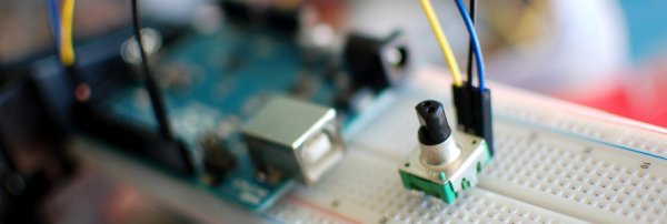
A rotary encoder is a device that you can rotate infinitely. Simple ones like this one I got from sparkfun have no real state like a pot does, so when you start up, you won’t be able to simply read from the encoder where it is turned to. But because you can keep turning it it has no beginning, middle or end anyways. However, if you keep track of that rotation in code, you can use it as a knob input you can turn up or down as much as you would like.
On most rotary encoders, when you rotate them, you will feel a bump. These are known as steps, and most rotary encoders like this guy have about 12 of these per rotation. But some have 200 or more. Basically this step is the minimum amount you can rotate the encoder to register any change.
Most simple encoders like this only make use of 3 pins, and one of those is ground. Those other two pins change state and are always either high or low, so they can only have a total of 4 combinations. 00, 01, 10, and 11. This is known as 2 bit gray code. So when you turn it, the arduino can say… Well you were at 01, and now you are at 00 so you move this way. Or you were at 01, but now you are at 10 so you must have moved the other way. You can see that this encoder has 5 pins, the other 2 are just a simple switch that is engaged when you press down. (see the second illustration on the right)
It sounds super simple, and it kinda is, but what we can do is every time a value changes we can check what direction it moved. Then if we increment a value every time it turned one way, and deincrement it when we move one step the other, we can keep track of how much it has moved since we started. So if you want a knob that can turn up to 11, this is your guy. (there is a double pun in there I promise)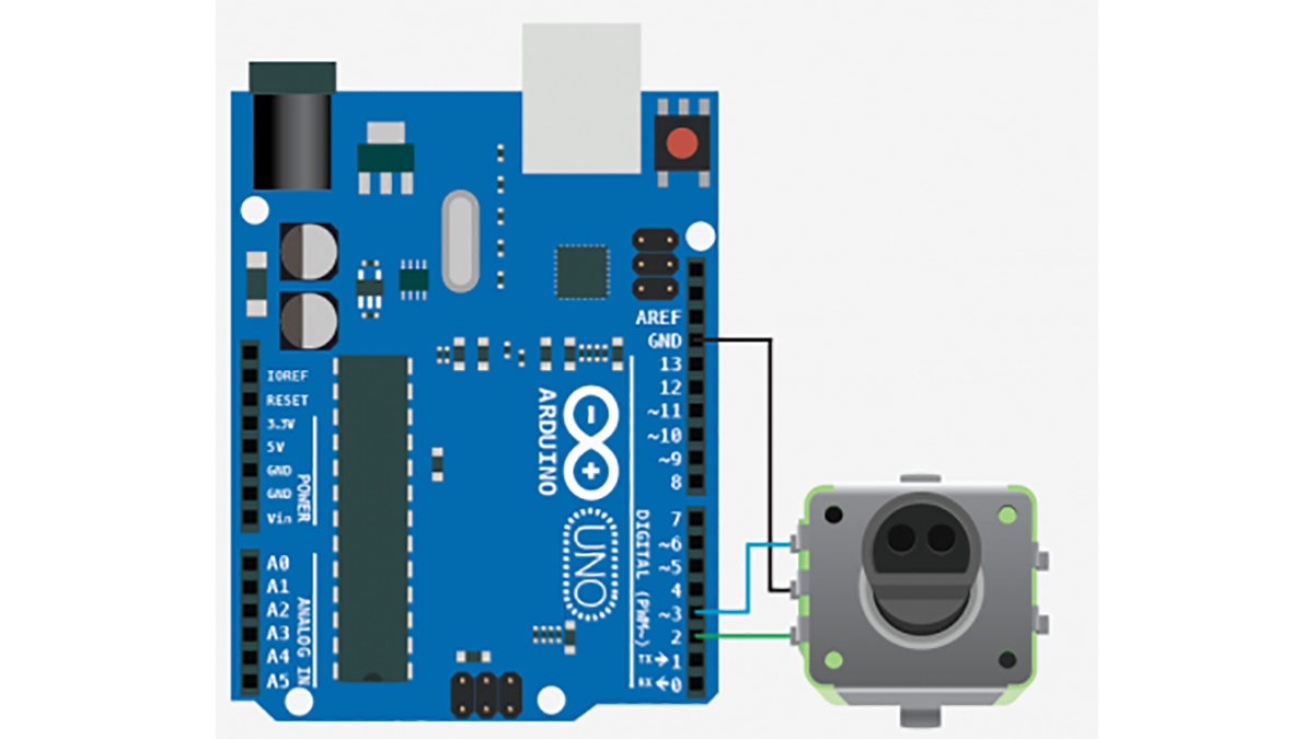
So, the really funky thing about a rotary encoder is for it to work, we need to know every time those values change. This can be hard because if the arduino is in the middle of doing something, like delay(1000) or what have you, we will miss the change. So we need a way to say to the arduino “I don’t care what you are doing, or when you are doing it, if you see any of these two pins change state, you drop everything and attend to them”. To do this we need something called interrupts.
For more detail: Rotary Encoder + Arduino
- What is a rotary encoder compared to a potentiometer?
A rotary encoder is an incremental device that can rotate infinitely and provides step changes, while a potentiometer provides an absolute position within a limited range. - How does a rotary encoder report movement?
It uses two output pins that change state in 2-bit gray code combinations (00, 01, 10, 11), allowing detection of direction by comparing previous and current states. - Can a rotary encoder tell the Arduino its absolute position at startup?
No, simple rotary encoders have no absolute state at startup; you must track rotation changes in code to determine position. - Why are interrupts needed for rotary encoder reading?
Interrupts ensure the Arduino responds immediately to changes on the encoder pins so it does not miss steps while busy with other tasks. - How many pins do most simple rotary encoders use?
Most simple encoders use three pins (ground plus two signal pins); some modules have two additional pins for a push switch. - What is a step on a rotary encoder?
A step is the tactile detent felt when rotating; it is the smallest rotation increment that registers a change, commonly around 12 steps per rotation for simple encoders. - How do you determine rotation direction with a rotary encoder?
By comparing the previous gray code state to the new state when a change occurs, you can infer whether the encoder moved clockwise or counterclockwise. - Can rotary encoders rotate indefinitely?
Yes, rotary encoders can rotate infinitely without a fixed start or end position.