
Summary of Room roving robot – phase 1 using arduino
The author modified a $10 RC jeep by integrating an Arduino with a Seeed Motor Shield V1.0 to create a controllable robot. The project involved stripping the original circuit board, repurposing the AA battery casing for motors, and mounting the electronics stack on the car's frame using electrical tape. A 9V battery was added to power the Arduino, while wires from an ARDX kit connected to the motor connectors.
Parts used in Room Roving Robot - Phase 1:
- $10 RC Jeep
- Arduino
- Seeed Motor Shield V1.0
- 3x1.5V AA Battery Casing
- Front steering motor
- Rear drive motor
- ARDX experimentation kit wires
- 9V Battery
- Electrical Tape
My second holiday project was a bit more fun than just blinking lights. I decided to tear apart a $10 RC jeep and control it with the Arduino. For this project, I added a motor shield on top of the Arduino that I purchased at the same Radio Shack where I found the RC car (Who would have thought that Radio Shack would get back to the hobby electronics game, after they seemed to be turning into a cell phone store!). The shield is the Seeed Motor Shield V1.0, which sits on top of the Arduino and passes through the Analog input pins as well as Digital pins 1 through 7. The shield is a bit clunky, because it has to sit on top of a shield stack but it served it’s purpose.
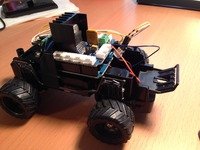 Starting with the car itself, I stripped it down to just it’s bare essentials, including clipping the battery connector wires off of the RC circuit board to remove that board (but reuse the 3×1.5V AA battery casing). The front steering and rear drive motors were connected to the RC board via nice little female connectors that happen to easily accept small gauge pins from the seeed ARDX experimentation kit I started this whole process using. The battery casing took a little finagling to get wire leads connected to the exposed leads, but I just pushed a long section of wire into the coils.
After snipping off a bit of plastic from the frame, I managed to get a pretty flat surface for the Arduino (with motor shield) to sit on top of. A little electrical tape, and bam… easy mounting is always the best for quick projects. I was also able to use the space directly above the rear drive motor to nestle a 9V battery that feeds the Arduino.
Here are some photos of the project:
The first photo shows the whole contraption with everything but the 9V battery attached (the little guy comes to life when that’s attached… I guess I need an on-off switch).
Next is the underside where you can see that I’m reusing the 3 slot battery casing for the motor power source. Also notice that little red dial on the front, which comes in handy. It’s a front wheel alignment device, which was needed after all the handling I did of the car to take it apart.
Next is a closer look at the electronic stack from the front of the car. This shows one of the female plugs from the motors, and how nicely the experimentation kit wires fit right into it.
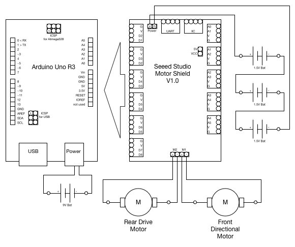 Last is the electronics stack from the rear of the car. The four wires coming out of the green terminals on the motor shield are the wiring for the two motors. The space above the rear drive motor that I use for the 9V battery that powers the Arduino is visible as well. You can also see that, when the 9V isn’t on the car, there’s easy access to the Arduino’s USB port for uploading programs.
For more detail: Room roving robot – phase 1
-
How did the author control the RC jeep?
The author controlled the RC jeep by tearing it apart and connecting it to an Arduino with a Seeed Motor Shield V1.0. -
What happened to the original RC circuit board?
The original RC circuit board was removed by clipping the battery connector wires, though the 3x1.5V AA battery casing was reused. -
Which kit provided the wires for the motor connections?
The female connectors on the motors easily accepted small gauge pins from the ARDX experimentation kit. -
How was the Arduino mounted on the car?
A bit of plastic was snipped from the frame to create a flat surface, and electrical tape was used to mount the Arduino and shield. -
What powers the Arduino in this setup?
A 9V battery is placed in the space directly above the rear drive motor to feed the Arduino. -
Why was a front wheel alignment device mentioned?
The red dial on the front is a wheel alignment device needed after handling the car during disassembly. -
Can you upload programs to the Arduino while it is on the car?
Yes, when the 9V battery is not attached, there is easy access to the Arduino's USB port for uploading programs. -
Does the project include an on-off switch?
No, the author noted they need an on-off switch since the car comes to life only when the 9V battery is attached.
