Summary of Remote control of a multi-light chandelier with Arduino
Summary: The author replaced a 15-bulb G4 halogen chandelier with low-voltage G4 LED bulbs, added a 220V-to-12V adapter, then integrated an Arduino Nano and IR remote to control bulb groups, patterns, and ambient-light autotoggle. They miniaturized the adapter PCB, implemented transistor switching, EEPROM state storage, and IR commands to provide individual/group switching, running-light effects, and adjustable light-threshold automation.
Parts used in the Arduino Magic Lamp project:
- Chandelier with 15 G4 two-pin bulb sockets
- G4 LED bulbs (12V, 2–3W each)
- 220V to 12V adapter (power supply, ~1.5 A continuous)
- Arduino Nano
- IR receiver module (connected to Arduino pin 10)
- IR remote
- Transistors cascade (D882 used for switching, labeled T1.1–T1.2)
- SMD components and prototype PCB for adapter rework
- Light-dependent resistor (LDR) or ambient light sensor (analog input A7)
- Feedback LED (connected to FEEDB_PIN, Arduino pin 12)
- Wiring and connectors for grouping bulbs into SG1–SG5 (3 bulbs per group)
- EEPROM (Arduino internal EEPROM used for storing settings)
Story:
It all began with a seemingly simple intention – replacing the bulbs in the chandelier adorning my bedroom. As you can observe in the accompanying image, the chandelier boasts an elegant design. Yet, a minor predicament emerged. To begin with, the fixture comprises a total of 15 illuminations and was initially crafted to accommodate G4 2-pin halogen bulbs. These petite culprits had an appearance akin to this:

These bulbs likely ranged from 15 to 20 watts each, offering no option for partial individual control within the chandelier. The only choice available was to either switch them all on simultaneously or turn them all off. Consequently, the chandelier’s operation amounted to a staggering power consumption of 225 to 300 watts. Adding to the predicament, the G4 halogen bulbs exhibited considerable unreliability, often failing within a span of mere months. Consequently, only a meager 7 to 8 bulbs remained operational at any given time.
However, matters took a turn for the better with the widespread adoption of LED technology. The bulbs pictured below performed the same task but with significantly reduced costs and energy consumption.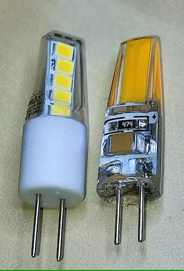
Each of these new bulbs consumes a mere 2-3 watts while providing a comparable level of illumination. Moreover, they are reputed to be considerably more dependable – at least in theory.
However, the reality proved somewhat different. Surprisingly, I found myself replacing these bulbs nearly as frequently as their halogen predecessors. The reasons behind this phenomenon remain uncertain. It’s possible that an issue with my installation was causing the bulbs to emit a faint glow even when switched off during nighttime hours. For a more in-depth exploration of this intriguing occurrence, you can delve into this informative article.
Additionally, sourcing warm light bulbs of this specific size for 220 volts posed a challenge. I found myself investing considerable time perusing Amazon in search of reasonably priced replacements. Eventually, my efforts paid off when I stumbled upon a promising deal – G4 LED bulbs, featuring 2 pins and emitting a warm light. Without delay, I placed an order for 30 units, only to realize later that they were actually intended for 12 volts, not the 220-volt setting I needed. Despite this mishap, they did offer an appealing aesthetic.

Upon linking them to a laboratory power supply, the readings consistently indicated 0.1 amp at 12 volts, translating to 1.2 watts per bulb. This calculation led to a total power consumption of 18 watts for all 15 lights – an impressively efficient outcome! Consequently, I arrived at the decision that an adapter facilitating the conversion from 220 volts to 12 volts was in order. My choice was guided by the requirement for a continuous output of approximately 1.5 amps, motivating me to acquire one of these adapters.

Upon removing the chandelier from the ceiling and inserting all the bulbs, the outcome was nothing short of ideal. The illumination emitted was consistently warm and unwavering, and the adapter capably managed the power demand of all 15 lights without a hitch. However, a rather perplexing obstacle surfaced – concealing the adapter behind the ceiling proved to be an insurmountable challenge, despite its relatively modest size. An unintended hiccup, indeed.
In a determined attempt to salvage the situation, I embarked on disassembling the adapter, holding onto the glimmer of hope that the electronic board could be extracted and integrated within the chandelier itself. Regrettably, this endeavor revealed that the board’s dimensions remained excessive for such integration. Frustration mingled with determination, leading me to a decision: I would painstakingly resolder the adapter onto a smaller prototype board, carefully tailored to snugly fit the chandelier’s confines. The subsequent phase proved far from straightforward – re-soldering the SMD components presented an arduous undertaking, a process I would strongly advise against attempting, unless you’re a seasoned expert.

Looking on the bright side, I stumbled upon a circuit diagram that closely resembled the adapter’s configuration, providing me with a newfound understanding of these intricate components.
Now, you might be wondering – where does Arduino fit into this narrative? Rest assured, the Arduino element is about to make its entrance. I invite you to stay with me as we journey onward. Before delving into the Arduino-related details, I couldn’t contain my elation as I witnessed the fruit of several weekends’ labor – my meticulously crafted circular adapter seamlessly springing to life.
In that very instant, an idea ignited within me. With a 12-volt supply firmly established, a sense of creative opportunity beckoned for my chandelier. The stage was set, with a compact circular compartment positioned just above the larger one I had dedicated to the adapter. The once-vacant space seemed tailor-made for the presence of an Arduino Nano.

And now, the moment calls for an exhilarating introduction. Enthusiasts and spectators, let’s give a warm round of applause to the Arduino Magic Lamp project. With the invaluable assistance of the Arduino IR remote, this project empowers you to:
Ladies and gentlemen, brace yourselves for the unveiling of the sensational Arduino Magic Lamp project. Equipped with the remarkable Arduino IR remote, this project bestows upon you the power to:
1. Seamlessly toggle individual or all chandelier bulbs on and off, or opt for an engaging running light display.
2. Effortlessly shift the lights’ pattern in a two-way motion, invoke inversions, or indulge in the mesmerizing running light effect.
3. Securely preserve your preferred light configuration within the realm of non-volatile memory.
4. Automate the chandelier’s activation or deactivation in response to the ambient illumination level of your space. Furthermore, you can customize the illumination threshold that triggers the chandelier’s illumination using the same IR remote. This threshold value is seamlessly stored within the non-volatile memory.
As a humorous aside, while I jest, I regret to inform you that the project does not include the capability to fetch beer from the nearest supermarket. (Please note: This is a jest and not an actual feature of the project.)
Displayed below is the circuit diagram for the lamp:
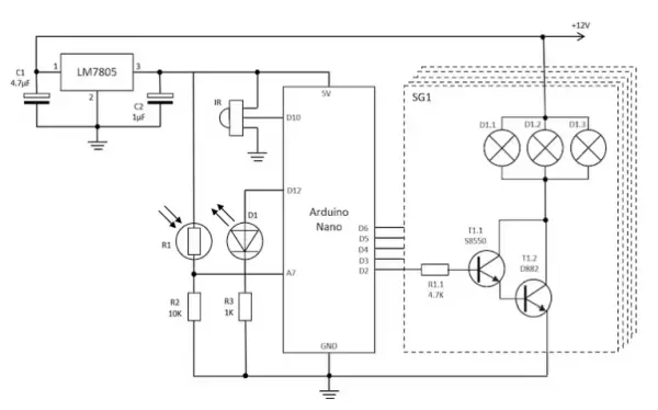
The depicted diagram showcases a design of utmost simplicity, devoid of any need for elusive components. With my chandelier encompassing a total of 15 bulbs, I opted to amalgamate them into distinct switching groups, designated as SG1-5, each accommodating three bulbs – a choice made to maintain straightforwardness.
For secure and dependable switching via Arduino’s digital output, a cascade of transistors, T1.1-1.2, has been orchestrated. While T1.2 has the potential for installation on a heatsink, my specific setup rendered this step redundant. Given that the open-state current it handles is a mere 0.1 Amp multiplied by 3, amounting to 0.3 Amps or 0.018 watts for the active transistor, the task proved effortless for the D882 transistor. It possesses a capacity to manage up to 1 watt of dissipation sans any cooling mechanism.
In my scenario, the Arduino digital outputs, D2-D6, orchestrated the switching process. Should the need arise, this number can be conveniently augmented to 10 with slight amendments to the Arduino sketch. Suffice it to say, this expansion comfortably accommodates the demands of most residential chandeliers.
The sketch for this project is below.
#include <IRremote.h>
#include <EEPROM.h>
const uint8_t POWER_BIT = 0xF;
const uint16_t POWER = 0x45;        // Power button (requires 3-sec long press for activation)
const uint16_t KEY_0 = 0x16;        // 1 light
const uint16_t KEY_1 = 0x0C;        // 101 light combination
const uint16_t KEY_2 = 0x18;        // 10101
const uint16_t KEY_3 = 0x5E;        // 11110
const uint16_t KEY_4 = 0x08;        // 11111 (all on)
const uint16_t KEY_5 = 0x1C;        // intro increasing right-to-left till all on state
const uint16_t KEY_6 = 0x5A;        // increasing left-to-righ till all on state
const uint16_t KEY_7 = 0x42;        // increasing to center till all on state
const uint16_t KEY_8 = 0x52;        // increasing from center till all on state
const uint16_t KEY_9 = 0x4A;        // running light then all on
const uint16_t KEY_UP = 0x09;       // shift up
const uint16_t KEY_DOWN = 0x07;     // shift down
const uint16_t KEY_VUP = 0x46;      // adding 1 light
const uint16_t KEY_VDOWN = 0x15;    // removing 1 light
const uint16_t KEY_ST_REPT = 0x0D;  // store config of lights in non-volatile memory
const uint16_t KEY_EQ = 0x19;       // invert lights
const uint16_t KEY_FF = 0x43;       // circular shift up (running light effect)
const uint16_t KEY_FB = 0x44;       // circular shift down
const uint16_t KEY_PP = 0x40;       // circular shift pause/play
const uint16_t KEY_FUNC = 0x47;     // func key for setting max/min amb light
const uint16_t VENDORID = 0xFF00;   // not used
const uint16_t ADDRESS = 0x0000;    // address of the device
const uint16_t ALL_ON = 0x801F;     // all on
const uint16_t ALL_OFF = 0x8000;    // all off
uint16_t command = 0x0;
uint16_t prev_command = 0x0;
uint16_t prev2 = 0x0;
const uint8_t MAX_COUNT = 0xF;
const uint8_t LONG_PRESS = 3;       // number of cycles a button need to be pressed to recognize long press
const int SAVED_STATE_ADDR = 0;
uint8_t com_count = 0;
uint8_t cycle = 0;
const int RECV_PIN = 10;            // Arduino pin where the IR receiver is connected
const int FEEDB_PIN = 12;           // Arduino pin where the IR feedback LED is connected
IRrecv irrecv(RECV_PIN);
const int STARTPIN = 2;
const int MAXPINS = 5;
const int MIDPIN = ceil(MAXPINS/2);
uint16_t state = ALL_ON;            // Bitfield for storing current state of the Magic Lamp.
const uint16_t DEFAULT_MAX_AMBLIGHT = 0xFFFF;        // default max ambient light (always on)
const int MAX_DISP = 0xA;                            // max disp
const int SAVED_MAXALGHT_ADDR = sizeof(uint16_t);    // address to save max
const int SAVED_MINALGHT_ADDR = 2*sizeof(uint16_t);    // address to save min
uint16_t max_amblight = DEFAULT_MAX_AMBLIGHT;        // maximum amblight threshold
uint16_t min_amblight = 0x0;                           // minimmum amblight threshold
uint16_t light_readings[MAX_COUNT];                  // stack of last amb light readings
void setup(){
 for(int i=0; i<MAXPINS; i++)
   pinMode(STARTPIN+i, OUTPUT);
 pinMode(FEEDB_PIN, OUTPUT);
 Serial.begin(9600);
//  Serial.println("Start IR");
 switchon();
 irrecv.enableIRIn();
}
int onCount() {
 int count=0;
 for(int i=0; i<MAXPINS; i++)
   if(bitRead(state,i)) count++;
 return count;
}
void blink(int times, uint16_t ms) {
 for(int i = 0; i<times; i++) {
   digitalWrite(FEEDB_PIN, HIGH);
   delay(ms);
   digitalWrite(FEEDB_PIN, LOW);
   delay(ms);
 }
}
void shift(bool up) {
     if(up) {
       bool buf = bitRead(state, MAXPINS-1);
       state = state << 1;
       bitWrite(state, 0, buf);
     }
     else {
       bool buf = bitRead(state, 0);
       state = state >> 1;
       bitWrite(state, MAXPINS-1, buf);
     }
     state = ALL_OFF + lowByte(state);
}
bool isplayable(uint16_t command) {
 return (command == KEY_FF) || (command == KEY_FB);
}
uint16_t get_run_avg(uint16_t light) {
 long total=0;
 for(int i=0; i<MAX_COUNT; i++) {
   if(i < MAX_COUNT-1) {
     light_readings[i] = light_readings[i+1];
     total += light_readings[i];
   }
   else {
     light_readings[i] = light;
     total += light_readings[i];
   }
 }
 return (uint16_t) round((float)total/MAX_COUNT);
}
uint16_t get_disp(uint16_t avglight) {
 long total=0;
 long delta=0;
 for(int i=0; i < MAX_COUNT; i++) {
   delta = (int)light_readings[i] - (int)avglight;
   delta = sq(delta);
   total = total + delta;
 }
 return (uint16_t) sqrt((float)total/(MAX_COUNT-1));
}
void reset_readings() {
 for(int i=0; i<MAX_COUNT; i++)
   light_readings[i] = 0;
}
void switchon() {
 EEPROM.get(SAVED_STATE_ADDR, state);
 if(onCount() == 0)
   state = ALL_ON;
 EEPROM.get(SAVED_MAXALGHT_ADDR, max_amblight);
 if(max_amblight == 0)
   max_amblight = DEFAULT_MAX_AMBLIGHT;
 EEPROM.get(SAVED_MINALGHT_ADDR, min_amblight);
 com_count = 0;
 cycle = 0;
 prev_command = 0;
 reset_readings();
}
void switchoff() {
 state = 0x0;
 cycle = 0;
 com_count = 0;
 prev_command = 0;
 reset_readings();
}
void set_min_amblight(uint16_t light) {
 min_amblight = light;
 EEPROM.put(SAVED_MINALGHT_ADDR, min_amblight);
 Serial.print("Min Light = ");
 Serial.println(min_amblight);
}
void set_max_amblight(uint16_t light) {
 max_amblight = light;
 EEPROM.put(SAVED_MAXALGHT_ADDR, max_amblight);
 Serial.print("Max Light = ");
 Serial.println(max_amblight);
}
void loop(){
 uint16_t light = get_run_avg(analogRead(A7));
 uint16_t disp = get_disp(light);
 Serial.print(" ");
 Serial.print(light);
 Serial.print(" ");
 Serial.println(disp);
 if (irrecv.decode()){
   if((irrecv.decodedIRData.protocol) == NEC && irrecv.decodedIRData.address == ADDRESS) {
     command = irrecv.decodedIRData.command;
     if(prev_command == KEY_FUNC and command != KEY_FUNC) {
       switch(command) {
         case KEY_0:
           set_max_amblight(DEFAULT_MAX_AMBLIGHT);
           set_min_amblight(0);
           blink(3, 200);
           break;
         case KEY_1:
           if(disp < MAX_DISP) {
             set_max_amblight(light);
             blink(3, 200);
           }
           break;
         case KEY_3:
           if(disp < MAX_DISP) {
             set_min_amblight(light);
             blink(3, 200);
           }
           break;
         case KEY_4:
           set_max_amblight(DEFAULT_MAX_AMBLIGHT);
           blink(3, 200);
           break;
         case KEY_6:
           set_min_amblight(0);
           blink(3, 200);
           break;
         default:
           blink(1, 50);
           break;
       }
       command = 0;
       com_count = 0;
     }
     else
       blink(1, 50);
     bool isOn = bitRead(state,POWER_BIT);
     if (isOn && (command == KEY_PP)) {
       if(isplayable(prev_command)) {
         prev2 = prev_command;
       }
       else if(prev_command == KEY_PP) {
         command = prev2;
       }
     }
     if (prev_command != command) {
       prev2 = prev_command;
       prev_command = command;
       com_count = 0;
     }
     else {
       if(irrecv.decodedIRData.decodedRawData == 0 && (com_count < MAX_COUNT) )
         com_count++;
       else
         com_count = 0;
     }
//      Serial.println(irrecv.decodedIRData.decodedRawData, HEX);
//      Serial.println(irrecv.decodedIRData.address, HEX);
//      Serial.println(command, HEX);
//      Serial.println(com_count, HEX);
     switch(command) {
       case POWER:
         if(com_count>1) {
           if(!isOn)
             switchon();
           else
             switchoff();
         }
         break;
       case KEY_0:
         state = 0x8001;
         break;
       case KEY_1:
         state = 0x8005;
         break;
       case KEY_2:
         state = 0x8015;
         break;
       case KEY_3:
         state = 0x800F;
         break;
       case KEY_4:
         state = 0x801F;
         break;
       case KEY_5:
       case KEY_6:
       case KEY_7:
       case KEY_8:
       case KEY_9:
         state = ALL_OFF;
         cycle = 0;
         break;
       case KEY_FF:
       case KEY_FB:
         break;
       case KEY_EQ:
         if(isOn && (onCount()<MAXPINS))
           for(int i=0; i<MAXPINS; i++)
             bitWrite(state, i, !bitRead(state,i));
         break;
       case KEY_UP:
         if(isOn) {
           shift(HIGH);
         }
         break;
       case KEY_DOWN:
         if(isOn) {
           shift(LOW);
         }
         break;
       case KEY_VUP:
         if(!isOn) bitWrite(state, POWER_BIT, HIGH);
         for(int i=0; i<MAXPINS; i++)
           if(!bitRead(state,i)) {
             bitWrite(state,i,HIGH);
             break;
           }
         break;
       case KEY_VDOWN:
         for(int i = MAXPINS-1; i >= 0; i--)
           if(bitRead(state,i)) {
             bitWrite(state,i,LOW);
             if((lowByte(state) & 0x1F) == 0)
               bitWrite(state, POWER_BIT, LOW);
             break;
           }
         break;
       case KEY_ST_REPT:
         if(isOn && com_count > LONG_PRESS) {
           // Long press, store current state
           EEPROM.put(SAVED_STATE_ADDR, state);
           com_count = 0;
           blink(3, 200);
//            Serial.println("State stored!");
         }
         if(!isOn) {
           // restore state from NVR
           EEPROM.get(SAVED_STATE_ADDR, state);
           if(!bitRead(state, POWER_BIT))
             state = ALL_ON;
         }
         break;
       default:
//          Serial.println("Not supported");
         break;
     }
   }
   irrecv.resume();
 }
 else {
   com_count = 0;
 }
 if(bitRead(state, POWER_BIT)) {
   switch(prev_command) {
     case KEY_5:
       if(cycle < MAXPINS )
         bitWrite(state, cycle, HIGH);
       else
         prev_command = 0;
       break;
     case KEY_6:
       if(cycle < MAXPINS )
         bitWrite(state, MAXPINS-cycle-1, HIGH);
       else
         prev_command = 0;
       break;
     case KEY_7:
       if(cycle < MIDPIN + 1 ) {
         bitWrite(state, MIDPIN + cycle, HIGH);
         bitWrite(state, MIDPIN - cycle, HIGH);
       }
       else
         prev_command = 0;
       break;
     case KEY_8:
       if(cycle < MIDPIN + 1) {
         bitWrite(state, cycle, HIGH);
         bitWrite(state, MAXPINS - cycle-1, HIGH);
       }
       else
         prev_command = 0;
       break;
     case KEY_9:
       if(cycle < MAXPINS ) {
         state = ALL_OFF;
         bitWrite(state, cycle, HIGH);
       }
       else{
         state = ALL_ON;
         prev_command = 0;
       }
       break;
     case KEY_FF:
       if(onCount()<MAXPINS) {
         shift(HIGH);
       }
       break;
     case KEY_FB:
       if(onCount()<MAXPINS) {
         shift(LOW);
       }
       break;
     default:
       break;
   }
 }
 if(bitRead(state,POWER_BIT) && (light > max_amblight) && (disp < MAX_DISP)) {
   switchoff();
 }
 if((!bitRead(state,POWER_BIT)) && (light < min_amblight) && (disp < MAX_DISP)) {
   switchon();
 }
 // Serial.println(state, HEX);
 // Write state to pins
 for(int i=0; i<MAXPINS; i++)
   digitalWrite(STARTPIN+i, bitRead(state, i));
 delay(700);
 if(cycle > MAX_COUNT || !bitRead(state,POWER_BIT))
   cycle = 0;
 else
   cycle++;
 if(!bitRead(state,POWER_BIT))
   digitalWrite(FEEDB_PIN, HIGH);
}
The operation is largely self-evident – during each cycle, Arduino evaluates the incoming IR commands and activates the appropriate lights as required. It’s worth noting that you might need to tailor the sketch to match your particular remote, as I utilized the resources at my disposal:
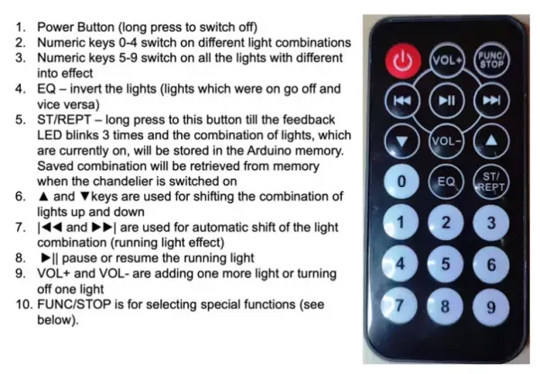
The potential to employ a universal remote is within reach, or you can customize the key codes directly within the Arduino sketch.
To unlock the special features enabling automatic chandelier activation or deactivation in response to ambient illumination, initiate the sequence by pressing FUNC/STOP, followed by a numeric key (a 3-time blink of the feedback LED confirms activation). The permissible numeric keys for this purpose are outlined below:
1. FUNC/STOP + 0 – Disables all forms of automatic on/off based on ambient light conditions.
2. FUNC/STOP + 1 – Captures and stores the existing ambient light level within the non-volatile memory. Subsequently, if the ambient light surpasses this recorded value, the chandelier will autonomously deactivate.
3. FUNC/STOP + 4 – Deactivates the automatic shutdown function based on the stored ambient value.
4. FUNC/STOP + 3 – Gauges and records the present ambient light level into the non-volatile memory. If the ambient light descends below this saved threshold, the chandelier will automatically activate.
5. FUNC/STOP + 6 – Disables the automatic power-up feature.
CAUTION: The power-up and shutdown functionalities are experimental in nature and their efficacy may vary based on your surroundings and the placement of the light-dependent resistor (LDR). Should the outcomes not align with your expectations, you can initiate a reset by pressing FUNC/STOP + 0 and recommence the process.
And there you have it! Embrace the experience. If this project resonates with you, please consider bestowing it a star or extending a donation – your support would be greatly appreciated 🙂
- Can the chandelier bulbs be individually switched?
Yes. The Arduino controls groups and individual bulbs via digital outputs mapped to STARTPIN..STARTPIN+4 allowing per-group and incremental control. - Does the project support running light effects?
Yes. The sketch implements multiple running and pattern effects (KEY_5..KEY_9, KEY_FF, KEY_FB) including left/right/center sequences. - How is ambient-light automation configured?
Use FUNC/STOP then a numeric key to set or disable max/min ambient thresholds; the values are stored in EEPROM and used to auto switch on/off. - What power supply is required for the 12V G4 LEDs?
The author used a 220V-to-12V adapter sized for about 1.5 A continuous to power all 15 bulbs. - Does the project store the preferred light configuration?
Yes. The current state can be saved to EEPROM with the store command (KEY_ST_REPT long press) and restored when off. - Can the number of controllable outputs be increased?
Yes. The sketch currently uses MAXPINS=5 but can be extended to up to 10 with minor sketch changes. - Is special hardware needed to switch the 12V LED groups from Arduino?
No exotic parts are required; a cascade of transistors (e.g., D882) is used to switch the groups safely from Arduino outputs. - How are IR remote codes handled?
The sketch decodes NEC protocol commands and maps specific remote command codes to functions; codes can be adapted to other remotes by editing the sketch. - What sensor input pin reads ambient light?
Analog input A7 reads the LDR/ambient light sensor values used for averaging and threshold decisions.