
Summary of Remote Control: ESP8266 With Coin Cell
This article details a low-power remote control for Philips Hue lights using an ESP8266 (Wemos D1 Mini) powered by a CR2450 coin cell. To overcome the high power surge required for Wi-Fi transmission, a supercapacitor is used to provide temporary peak current. The project involves hardware assembly with specific components, 3D printing a custom case, and configuring Arduino code with static IP settings to communicate with a Hue bridge.
Parts used in the Remote Control ESP8266 With Coin Cell:
- Wemos D1 mini
- Coin Cell CR2450
- Coin Cell Socket
- Supercap 3.3F 3.0V
- Resistor 120 Ohm
- wires
- Soldering iron
- 3D Printer or small case
The big problem using the ESPs is the power consumption when Wifi “goes up”, about 100-200mA, peak up to 300mA. Normal coincells deliver a few mA, peak up to 20-40mA. But for the ESPs the voltage will collapse. We need “a little help of my friend”: the supercap. These capacitors deliver enough current for power up the Wifi and sending a message, in this case the switch command. Another option is a datalogger that have to wake up every few hours for a couple of seconds.
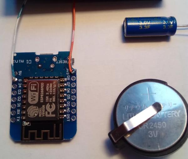
In this instructable i use the Esp8266 to build a remote control for phillips hue lights.
Step 1: The Solution

First of all we have to know that it is no good idea to connect the battery and cap simply parallel.
The charging current from cell to cap has to be reduced with a resistor. The specs for my coin cell tell us a peak current of 25mA.
Ohm’s law: R=U/I -> 3V/25mA= 120 Ohm.
The supercap has enough capacity to power the ESP for 10-20 seconds. If you use a static ip address like i do, the ESP only wake up for 1-2 seconds sends/receive its message and fall into “deepsleep” until the reset button is pressed.
Two options for the schematic:
1. Connect the supply directly and use the reset switch for action, see picture. In this case we have to make sure that the wemos needs as little power as possible, so we may have to remove the 3.3V regulator and the supply for the uart-ic.
2. We use a button switch that seperates the supply from the wemos. The downside is that you have to press the button for 1-2 seconds until the action is done. (lights on or off)
Step 2: Part List
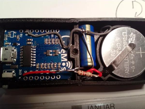
Primary Requirements:
- Wemos D1 mini
- Coin Cell CR2450
- Coin Cell Socket
- Supercap 3.3F 3.0V use one with little leakage current
- Resistor 120Ohm
- wires
Secondary Requirements:
Soldering iron
3D Printer for printed case
or
any other small (used)case
or
wall switch
Step 3: 3d Printed Case
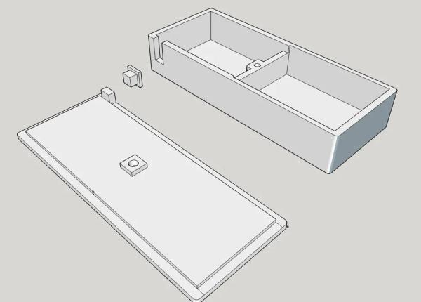
Here are some stl files for a small case into which the board fits exactly
I use normal print settings with an infill of 30% and 0.2mm layer height.
The knob is also printed so you can use the reset button for action and don’t has to use an extra button.
Use skirt and brim for the knob because the object is very small
Step 4: Coding the Esp8266
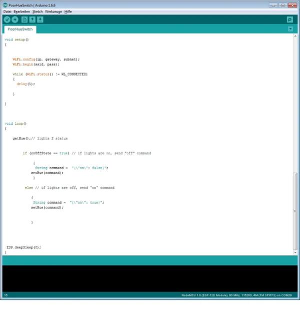
First you need the Arduino IDE.
Then you have to install the library for Esp8266.
You’ll find several tutorials here on instructables how to program these magic tiny things 🙂
For a faster connecting/switching we use a static ip adress.
After opening the attached sketch with the Arduino IDE you have to do some settings depending to you local WIFI.
IPAddress gateway(192,168,178,1);
ip adress of you local wifi router where the hue bridge is connected
IPAddress ip(192, 168, 178, 216);
Ip adress of your switch, be aware of using a high adress in the range of 200-250 that is not used for other devices
IPAddress subnet(255,255,255,0);
int light = 2;
the number of your light that is switched
const char hueHubIP[] = “192.168.178.57”;
the ip adress of the hue bridge
const char hueUsername[] = “hue bridge username”
you have to create an authorized username in the hue bridge, look at this tutorial
const int hueHubPort = 80;
always “80”
const char ssid[] = “SSID“; // network SSID (name)
const char pass[] = “password”;// network password
finally SSID and password of your wifi
After changing these settings you are ready for upload !
Step 5: Final Steps and Thoughts
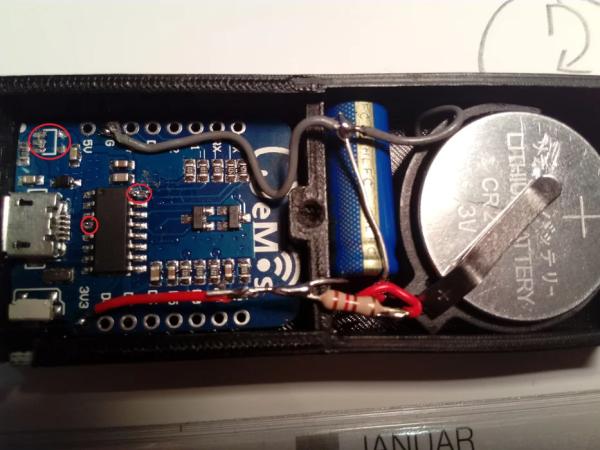
Be sure to pre-charge the cap before connecting to wemos because the Esp8266 immediately start to make a wifi connection after reset/connect power.
See assembly in video
to save energy disconnect pin 4 and 16 of uart-ic and remove the
voltage regulator, please note after that it’s no longer possible to program the wemos via USB !!
Source: Remote Control: ESP8266 With Coin Cell
- Why is a supercapacitor needed for this project?
The supercapacitor provides enough current to power up the Wi-Fi and send messages because normal coin cells cause voltage collapse during the 100-300mA peak draw of the ESP. - How do you calculate the resistor value for charging the capacitor?
You use Ohm's law (R=U/I) where 3V divided by the 25mA peak current of the coin cell results in a 120 Ohm resistor. - What are the two schematic options for connecting the supply?
Option 1 connects the supply directly and uses a reset switch, while Option 2 uses a button switch that separates the supply from the Wemos until pressed. - How can you minimize power consumption on the Wemos board?
You can remove the 3.3V regulator and disconnect pins 4 and 16 of the uart-ic, though this prevents programming via USB. - Why should you pre-charge the capacitor before connecting it to the Wemos?
The ESP8266 immediately starts making a Wi-Fi connection after reset or power connection, so pre-charging ensures stable operation. - What IP address range is recommended for the switch?
It is advised to use a high address in the range of 200-250 that is not currently used by other devices. - What port number is used for the Hue Hub communication?
The constant hueHubPort is set to 80. - How long does the supercapacitor capacity last for the ESP?
The supercap has enough capacity to power the ESP for 10-20 seconds.
