
Summary of Reflow Oven Controller with graphics TFT
This Arduino-based reflow oven controller provides PID and phase/wave packet AC control, graphical TFT temperature plotting, rotary-encoder-only UI, and stores up to 30 temperature profiles in EEPROM. Hardware supports two independent temperature measurements and two AC loads (heater and fan), uses an Adafruit 1.8" TFT, Arduino Pro Micro, MAX31855 thermocouple converters, and Sharp S202S01 SSRs. Warning: project works with mains voltage.
Parts used in the Reflow Oven Controller:
- Arduino Pro Micro (Leonardo-like)
- Custom shield / motherboard PCB
- Adafruit 1.8" TFT or derivative display
- Rotary encoder with single button
- MAX31855 thermocouple-to-digital converter (up to two)
- Thermocouples (K-type implied)
- Sharp S202S01 PCB-mount solid state relays (two)
- Fischer SK409 50.8 heat sinks (for SSRs)
- Zero crossing detection circuit components
- Power and connector components for mains wiring
Reflow Oven Controller
Arduino-based reflow oven controller with:
- PID loop control
- Wave Packet and Phase Fired control for AC outputs
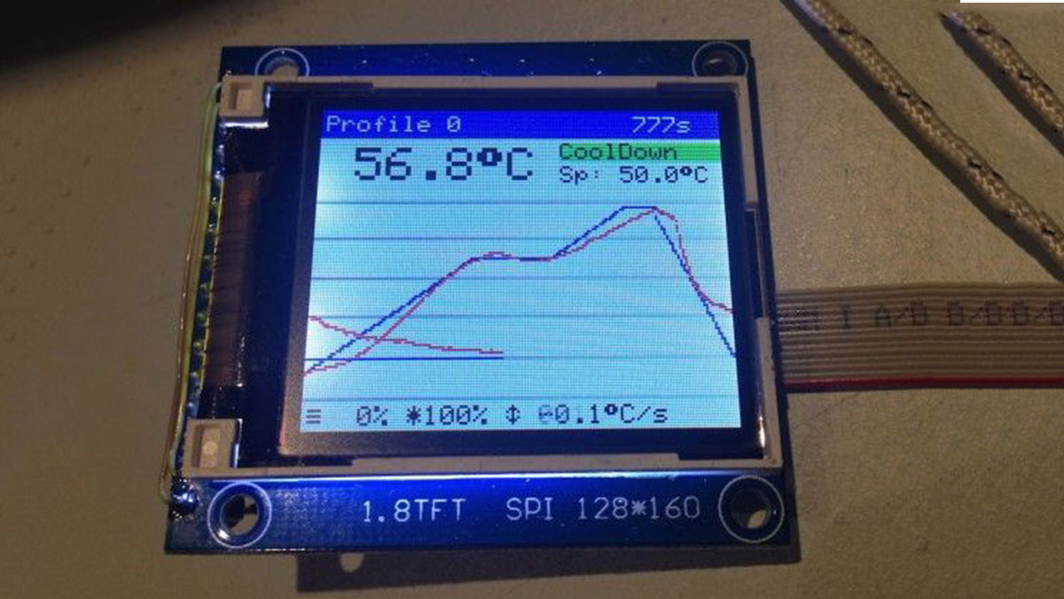
- graphic TFT LC-Display, drawing the temperature curves
- using an Adafruit 1.8″ TFT or derivate display
- solely controlled using a cheap rotary encoder and it’s single button
- stores up to 30 temperature profiles in EEPROM
- configurable PID-parameters
- simple, small hardware to drive loads up to 600V and up to 8A
- hardware can
- measure two temperatures independently
- drive two AC loads, such as heater and fan
- could also be used for slow coockers
(c) 2014 Karl Pitrich [email protected] in part based on a project (c) 2013 Ed Simmons [email protected]
Warning: This project operates with possibly lethal mains voltage. If you are unsure what to do, don’t do it and get help from an experienced tinkerer with professional training.
Post action shot:
Introduction
This Reflow Oven Controller relies on an Arduino Pro Micro, which is similar to the Leonardo and easily obtainable on eb*y for less than $10, plus my custom shield, which is actually more like a motherboard.
As I believe it is not wise to have a mess of wiring and tiny breakout-boards for operating mains powered equipment, I’ve decided to design custom board with easily obtainable components.
The hardware can be found in the folder hardware, including the Eagle schematics and PCB layout files. It should fit the freemium version of Eagle. Here are preview images:
From my manufacturing run, I have some spare PCBs. You can contact me to get some (€15,- + p&p each).
The board contains the Arduino Pro Micro, very simple Zero crossing detection circuit, used to align control logic to mains frequency, two MAX31855 thermocouple-to-digital converters and two Sharp S202S01 PCB-mount solid state relays, mounted on cheap Fischer SK409 50,8 heat sinks. The current software uses only one of the thermocouples, so you need to populate one IC only. If you’re lucky, you can get free samples of the MAX31855 from Maxim.
For more detail: Reflow Oven Controller with graphics TFT
- What microcontroller is used in the project?
The project uses an Arduino Pro Micro, similar to the Leonardo. - Can the controller display temperature curves?
Yes, it uses a graphic TFT display (Adafruit 1.8" or derivative) to draw temperature curves. - How many temperature profiles can be stored?
The controller can store up to 30 temperature profiles in EEPROM. - How is the controller operated by the user?
It is solely controlled using a rotary encoder and its single button. - How many temperatures and loads can the hardware handle?
The hardware can measure two temperatures independently and drive two AC loads such as heater and fan. - What thermocouple converter is used?
The design uses MAX31855 thermocouple-to-digital converters. - What type of solid state relays are used?
The project uses Sharp S202S01 PCB-mount solid state relays. - Does the project include mains synchronization?
Yes, the board includes a very simple zero crossing detection circuit to align control logic to mains frequency. - Can the hardware be used for other appliances?
Yes, it could also be used for slow cookers according to the article. - Is there a warning regarding safety?
Yes, the article warns the project operates with potentially lethal mains voltage and recommends seeking experienced help if unsure.
