Summary of Quick and Easy Arduino Nightlight
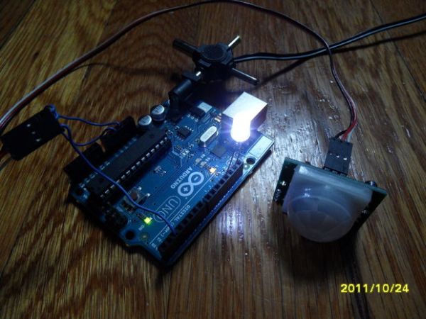
This article describes a DIY Arduino-based nightlight that activates when motion is detected, solving the problem of finding light switches in the dark. The project uses a Parallax Passive Infrared (PIR) sensor to trigger an LED for seven seconds after detecting movement, featuring a 30-second calibration period and safety insulation to prevent false triggers.
Parts used in the Arduino Nightlight:
- Arduino
- Parallax PIR Motion Sensor
- Ultra Bright White LED
- Jumper wires
- Optoisolator/optocoupler/relay
- Resistor
Honestly, how many people have been in this scenario (leave a yes or no in the comments) : It is 2:30 in the morning and you wake up with a need to do something whatever that may be (bathroom, forgotten homework assignment, project due in 5 or 6 hours, etc.) it takes you 5-10 minutes to find the light switch (give or take…)
My mother likes a night light for the bathroom but she didn’t want one that stayed on all night so I needed one that could detect a person. Many thoughts popped up into my head on what sensors to use. I could us esuch as the Linescan Imaging Sensor Daughterboard by Parallax but that was overkill and too expensive. A cheaper solution would be to use a few ir leds with ir phototransistor but still too complicated. I also thought of the Ping Sensor from Parallax but too hard to program with my beginner standards in C and, it used too much power. (I’m more of a Spin and Assembly language person.) I finally looked through my sensors box and found…(…drumroll please…) …Parallax’s Passive Infared Motion Sensor! It was fairly inespensive ($9.99), it could work in the dark, and, I have had experience in programming these!
Step 1: Get The Required Materials.
1 of everything except where noted.
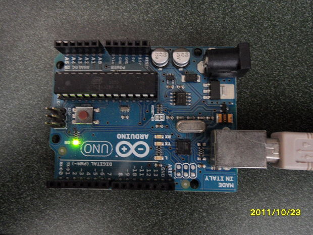
Arduino
PIR Motion Sensor from Parallax
LED ( Preferably Ultra Bright White. I bought mine along with other colors at Ebay from this seller: http://myworld.ebay.com/led.shop*2010/?_trksid=p4340.l2559
They will compile your own personal mix of colors if you want them to…they will charge more but it is a personalized order. I also found this order of only white LEDs but very cheap.
http://www.ebay.com/itm/100pcs-5mm-Ultra-Bright-White-LEDs-200pcs-resistors-/220610858794?pt=LH_DefaultDomain_0&hash=item335d6e8f2a#ht_2715wt_1017
Many jumper wires
Optoisolator/ optocoupler/ relay
Resistor. Define the value yourself.
Step 2: Program.
Program the code into the Arduino.
This will make the Arduino read the sensor’s output and trigger an LED for seven seconds and turn off. Modify to meet your needs. It takes 30 seconds to calibrate the sensor.
Use this link and download open the editor and program.
https://www.rapidshare.com/#!download|833tl3|3411132297|Sketch.pde|1|R~2964C5D605113ECA37CDDB4ED2C02EFB|0|0
If you have trouble…here it is!
//be sure the project box is insulated or false motion triggers will happen
int calibrationTime = 30;
int Time = 0;
long unsigned int lowIn;
long unsigned int pause = 5000;
boolean lockinHigh = false;
int LEDsop = 13; // pin 13 includes resistor sop- signal out pin
int outpin = 12; // for any other device that doesn’t require resistor
int SensorInpin = 2; // can vary, must be digital from 1-12
boolean sensorready = false;
void setup (){
pinMode (LEDsop, OUTPUT);
digitalWrite (LEDsop, LOW);
pinMode (outpin, OUTPUT);
digitalWrite (outpin, LOW);
pinMode (SensorInpin, INPUT);
pinMode (0, INPUT);
pinMode (1, INPUT);
pinMode (3, INPUT);
pinMode (4, INPUT);
pinMode (5, INPUT);
pinMode (6, INPUT);
pinMode (7, INPUT);
pinMode (8, INPUT);
pinMode (9, INPUT);
pinMode (10, INPUT);
pinMode (11, INPUT);
do {
digitalWrite (LEDsop, HIGH);
delay (500);
digitalWrite (LEDsop, LOW);
delay (500);
Time = Time + 1;
}
while (Time < calibrationTime);
digitalWrite (LEDsop, LOW); //if led turns off, sensor is ready
sensorready = true;
}
void loop (){
if (sensorready == true){
if (digitalRead(SensorInpin))
{
digitalWrite (LEDsop, HIGH);
digitalWrite (outpin, HIGH);
delay (7000); //modify to meet your required delay time
digitalWrite (LEDsop, LOW);
digitalWrite (outpin, LOW);
delay (250);
}
}
}
Step 3: Assemble.
Plug the sensor’s power pin (red) to 5 volts, the ground (black) to ground and the signal (white) to digital pin 2.
Add the LED to Pin 13. Make a note of it as in the troubleshooting step I will discuss this.
Solder (or breadboard the optoisolator if you need any more than one LED to turn on.) This is connected to Pin 12.
Use the relay if necessary. This is also for Pin 12.
Make sure the sensor’s jumper is towards the H position.
For more detail: Quick and Easy Arduino Nightlight
- Why did the author choose the Parallax PIR sensor?
The author selected it because it was inexpensive at $9.99, works in the dark, and they had prior programming experience with it. - How long does the sensor take to calibrate?
The sensor requires 30 seconds to calibrate before it becomes ready to detect motion. - What happens after the sensor detects motion?
The system triggers an LED for seven seconds before turning off automatically. - Which digital pin should the sensor signal wire connect to?
The signal wire from the sensor must be connected to digital pin 2. - How can I prevent false motion triggers during assembly?
You must ensure the project box is insulated to avoid false triggers caused by internal reflections or heat. - What position should the sensor's jumper be set to?
The sensor's jumper must be positioned towards the H setting for proper operation. - Can this project control devices other than LEDs?
Yes, you can connect other devices like relays to Pin 12 using an optoisolator if more power is needed. - What programming language was considered but rejected for this project?
The author initially considered C for the Ping Sensor but rejected it due to complexity and high power usage.