Arduinos are incredibly useful tools for all sorts of projects. Given the current COVID-19 pandemic, having easy, fast, cheap, and reliable access to health information is more important than ever. While an Arduino might not be the tool of choice for proper medical applications, we can draw inspiration from medical devices to create fun and interesting projects, which is the goal of this tutorial. In the following steps, you’ll learn how to make your own pulse oximeter, which measures blood oxygen levels, and heart rate monitor. These values will be shown on a screen, and your blood oxygen level will also be shown off with visual cues to help determine if it’s in an acceptable range. This project is relatively simple but is still a fun way to learn more about the uses of Arduino components.
Step 1: Quick Disclaimer
It should be stated that this device is not reliable or accurate enough to be used as a medical diagnosis or reference, and should not be used in that way. It is simply a fun project to show off the capabilities of an Arduino and a few other parts.
Step 2: Gather Supplies
Below is a list of things you’ll need for the project, along with a link to buy the item.
Arduino Nano (1)
Breadboard (1)
MAX30102 Sensor (1)
I2C OLED Screen (1)
2 LEDs (one red and one green, or whichever colors you prefer)
Jumper wires (11)
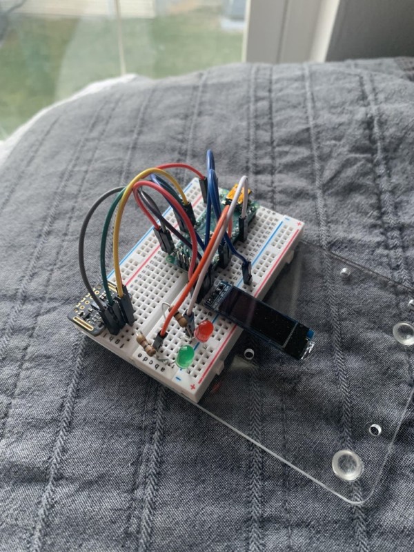
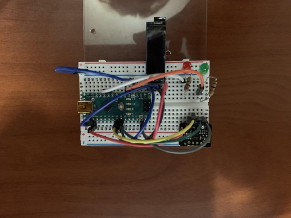
Step 3: Assemble the Components
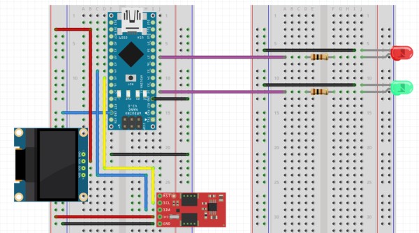
Following the breadboard diagram, wire up the components as shown. The Arduino Nano is the large blue block on the upper left, the OLED screen is the black block on the far left, and the MAX30102 sensor is the red block on the bottom. In our wiring and code, the LEDs are connected to Digital Pins 2 and 7 on the Arduino, however you can change this to whichever pins you prefer. If you do, make sure you also alter the code to match! Also make sure you use the 3.3V output from the Arduino and not the 5V, as accidentally using the 5V could damage the screen or MAX30102 sensor. Do your best to color code the wires, such as using red jumper wires for power connections and black wires for ground connections. This will help to keep the circuit neat and easy to understand.
When assembling, there are a few key things to keep in mind. First, do not power the Arduino until the wiring is completed and double-checked, and do not leave the Arduino powered while fixing connections on the breadboard. Also, ensure that the LEDs are in the proper orientation: the longer leg (anode) of the LED is the positive side and should be connected to the Arduino pins and resistor, while the shorter side (cathode) should be connected to ground.
Step 4: Upload the Code
The code required for this to work is provided below. In order to use this code, you’ll need the Arduino IDE downloaded on your computer, as well as the relevant libraries required for the components. For an explanation of Arduino libraries, follow this link. The libraries needed for this project are the ‘Sparkfun MAX3010x’ library, the ‘Adafruit SSD1306’ library, and the ‘SSD1306Ascii’ library. You can download these from within the Arduino IDE by selecting ‘Tools’ in the top right, then selecting ‘Manage Libraries…’, which will bring you to the library manager. From there, use the search bar to search for the necessary libraries and download the latest versions of each.
Although the code will work without any additional input or changes, it’s a good idea to go through the code and read the comments to get an understanding of what the code is actually doing and how it all works. The code is thoroughly commented on, so it should be easy to get an idea of what’s happening.
The majority of this code comes from an open-source project from the Arduino Project Hub, found here. Changes were made to accommodate the hardware specific to this project, as well as integrating the LED status indicators.
Once you’ve downloaded the required libraries and read through the code, connect your Arduino to your computer and upload the sketch. For help with this, see this article.
Step 5: Use It!
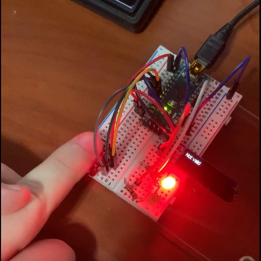
Now that the parts are assembled and the sketch is uploaded to the Arduino, the pulse oximeter is ready to be used! Simply place the tip of your finger over the pulse oximeter sensor (it shines with a red light, you can use this as a guide for where to place your finger) and wait for your heart rate and SP02 to show on the screen! Or, if you don’t want to look at the screen, you can refer to which LED lights up. If the green LED is lit, your SP02 is in a good range!
Source: Pulse Oximeter and Heart Rate Monitor