You must have seen many magic tricks and wondered how it works so, here’s another one but you don’t have to figure out how it works. I will show how it works (Spoiler – It uses magnets and some electronics) and how you can make one yourself.
This magic Spinning Top rotates forever and you may think it is perpetual motion but it isn’t so I call it Pseudo Perpetual Spinning Top
Supplies
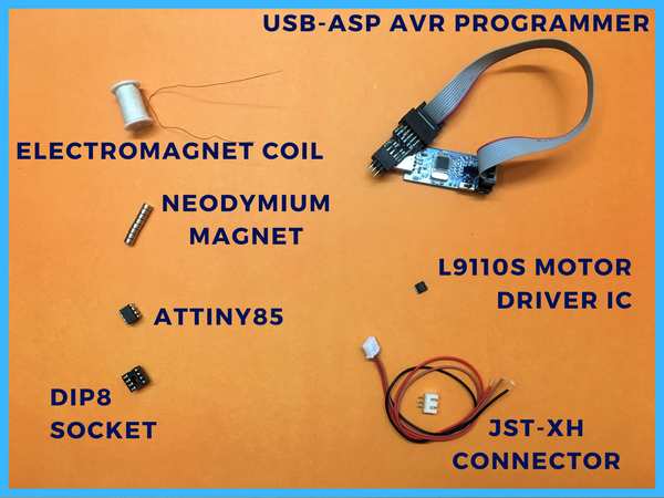
Components
- Attiny85
- 49E Hall Sensor
- LiPo Battery
- TP4056 Battery Protection and Charge Circuit
- 3.3V to 5V Boost Converter
- SPDT Switch
- USB-ASP AVR Programmer
Software
- Arduino IDE
Hardware
- 3x5mm Round Neodynium Magnet
- Electromagnet(Buy or Make one yourself – Detail in Step)
- 34-37 Guage Enamel Copper Wire
- 2mm Non-Metallic Rod
- Some 3D Printed Parts
- SandPaper for sanding 3D Printed Parts
- 3D Printer (Optional)
- DoubleSided Tape
- Glue Gun
Step 1: Science Behind the Magic
The perpetual top uses a few permanent neodymium magnets which lie inside the spinning top and an electromagnet that resides in the base i.e., the platform on which the spinning is rotating, and a Hall Effect Sensor that detects the polarity of the magnet in the spinning top and triggers the Electromagnet.
You can see this in the animation above; as soon as the North pole(Red) appears above the Hall Effect Sensor, it triggers the polarity of the Electromagnet such that the South Pole(Blue) is on the top side of the Electromagnet so that it will attract the spinning top and this gives a bit of acceleration to the spinning top. This triggering happens twice every rotation, one for the NorthPole and one for the South Pole, and that’s how the spinning top gains enough stability to rotate forever (or as long as the Electromagnet’s polarity keeps on changing on time).
Step 2: Electronics and Circuit
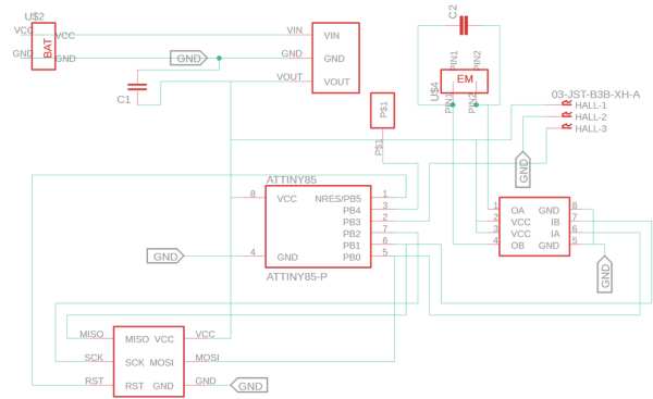
The Circuit and the PCB for this project s designed in the Eagle CAD.
Attiny85 is used to read the value from the Hall Effect Sensor and a Motor Driver L9110S to drive the Electromagnet Coil in both Polarity.
This Circuit runs from a Lipo Battery so a Boost Converter is Used to step up the voltage from 3.2-4.2V from the battery to 5 V required for the Circuit and the Coil.
Apart from the Circuit TP4056 Lipo Protection and Charge Circuit is sued to charge and safely discharge the battery.
Step 3: PCB Manufacturing From PCBWay.com
After creating the schematic and board design, rather than troubling myself with homemade PCBs, I generated the Gerber File (you can download it from this link) and ordered from the quick PCB Prototyping service of PCBWay.com. Ten pcs of professional-made PCBs arrived at my home within a few days.
Step 4: Electromagnet
You can buy an Electromagnet or even a wound one for yourself.
You will require enameled copper wire of 34-28 Guage ( I used 35 Guage).
Then I printed some stoppers that I put over the rod, so the coil is wound within a given range.
To quickly wound the coil, I used a small geared motor that has good torque and attached a chuck to hold the coil rod and wound the coil approximately 10 meters in length. The resistance of the coil after the wounding comes out to be 11Ohms.
Step 5: PCB Assembly
Start With the soldering of SMD parts first then move the Through Hole parts.
there are Pads for Battery connection and Electromagnets.
For the Boost Converter, you can use the special 3.3v to 5V Step-Up Converter which comes in 3 Pin configuration or you can use the standard boost converter and attach the input pin to Vin, ground to GND, and output to Vout. Just make sure the boost converter can supply at least 500mA.
Step 6: Attiny85 Programming
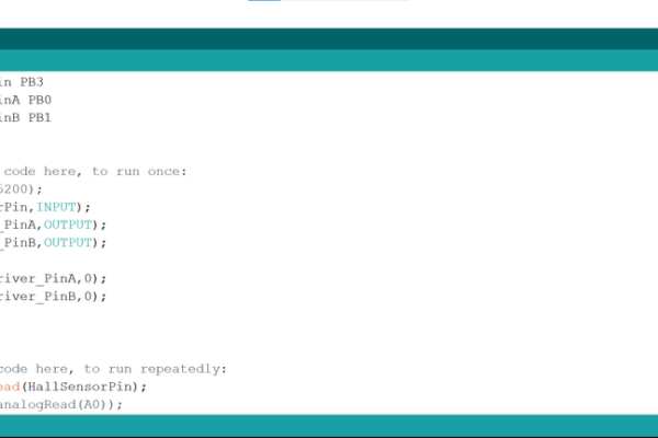
If Attiny Boards are not installed in the Arduino IDE then first install the ATTINY Boards in the IDE through this link
After the Arduino Boards are installed then upload the code using USB-ASP AVR Programmer or Arduino Uno.
you can program the IC using the ISP Connector on the PCB or you can program it alone and then install it on the PCB.
Step 7: 3D Print
The 3D Model for this project is designed in Fusion 360 and there are four parts needed to be 3D Printed for the enclosure and the spinning top which will be holding the permanent magnets.
All the parts are listed below and I have also included the Fusion 360 File which you can tweak to your needs if required.
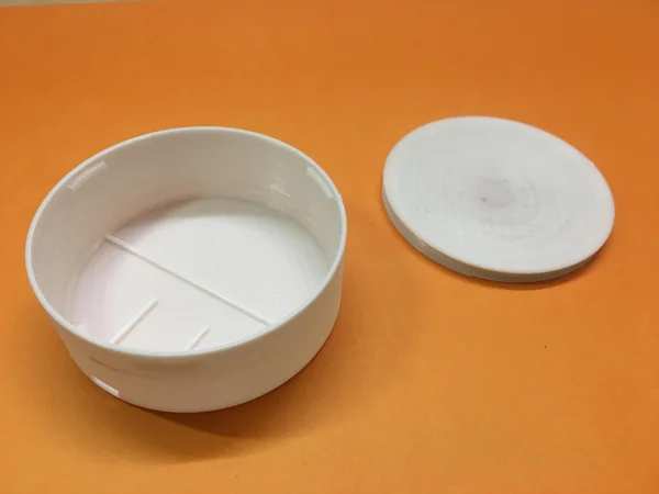
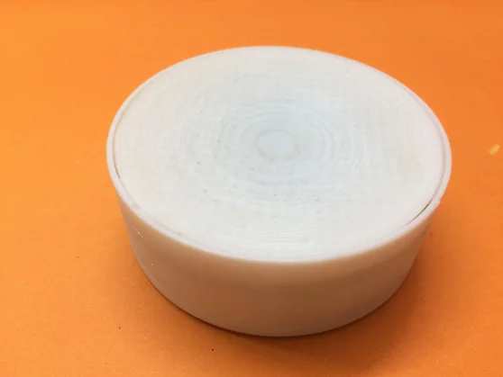
Step 8: Spinning Platform Preperation
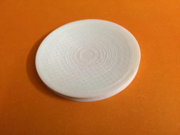
The Spin Platform is a curved platform and the curve is provided so the spinning top can rotate in a given region where it is in range with the sensor as well as the electromagnet.
and it is recommended to print it at will 0.1mm layer height for better results. After printing the platform you can use sandpaper to smooth out the layers and create a seamless transition between the layers so the spinning top can rotate feeling on the base.
Step 9: Spinning Top Assembly
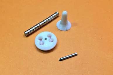
The Spinning top will require 8 neodymium magnets.
4 magnets on each side of the spinning top, and the polarity of the magnets will be opposite on the other side as can be seen in the image/animation where blue is the SouthPole and Red is the NorthPole.
After adding the magnets in the holes cover it using the top part which will act as a handle for the spinning top to rotate.
Then add a 2mm pointed rod into both the parts. If the rod feels loose then use some adhesive like super glue or a glue gun.
In the animation, only 4 magnets are been shown but you can add more to increase the magnetic strength so the top position can be easily sensed by the Hall Effect Sensor.
Step 10: Assembly Animation
This animation is just for your reference to show what will go where during the assembly.
Step 11: Solder Batteries and Switch
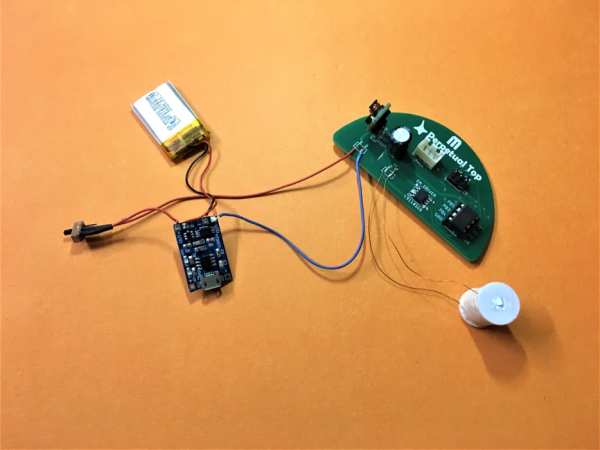
After assembling the PCB, we need to solder the battery, Switch and the electromagnet to the PCB before the final assembly
Step 12: Final Assembly
First, attach the hall Effect Sensor to the bottom of the Spin Platform such that its sensing part is near to the center of the circular base using double-sided tape and
Then attach the PCB to the enclosure body in the given position and secure it using a glue gun or double-sided tape.
Then connect the electromagnet, battery, SPDT On/Off Switch, and TP4056 Charge Circuit to their respective position.
Electromagnet
First, attach the electromagnet temporarily to the body as its position needs to be adjusted in order to find the optimum position according to the electromagnet and neodymium combination used by you.
It is a little Hit and Trial method where you need to find the position where the rotation of the spinning top is the best.
Then finalize that position and secure it using a glue gun.
Step 13: Show the Magic
You are ready to show the trick to your friends and family and see their reactions.
It can be a fantastic showpiece on your table.
If you made it, do share it below and if you face any issues during the build, send me a message. I’ll love to help you out.
Source: Pseudo Perpetual Spinning Top