Summary of PS1 Controller Joysticks with Arduino
This article details a project to extract the dual thumbstick mechanism from an old PlayStation 1 controller for use with an Arduino. The goal is to utilize the analog potentiometers and buttons directly without requiring extra libraries or drivers, creating a compact input solution for projects like wireless robots.
Parts used in the PS1 Controller Joysticks with Arduino:
- Playstation 1 controller
- Soldering Iron
- Solder
- Knife
- Wire strippers/cutters
- Electrical Tape
- Small Phillips head screwdriver
- Two mid-value resistors
- Third Hand tool
- 22 gauge wire
Please let me know what you think or if you have questions/criticism for me! I’m always looking to learn new things.Required materials:
~ Playstation 1 controller
~ Soldering Iron
~ Solder
~ Knife
~ Wire strippers/cutters
~ Electrical Tape
~ Small Phillips head screwdriver
~ Two mid-value resistors (for pushbutton cicuits)
~ Third Hand (not absolutely necessary but makes soldering small things much much easier)
~ 22 gauge wire
Video Demo:
const byte leftClick = 2; //assign the pins for the buttons
const byte rightClick = 3;
const byte leftVert = A2; //assign the pins for the pots
const byte leftHor = A3;
const byte rightVert = A0;
const byte rightHor = A1;
int delayTime = 50; //so the serial output is more readable
void setup(){
pinMode(leftClick, INPUT); //set button pins to input
pinMode(rightClick, INPUT);
Serial.begin(9600); //lets arduino send text to computer
}
void loop(){
//output formatted as leftHorizontal, leftVertical, leftButton, rightButton, rightHorizontal, rightVertical
Serial.print(analogRead(leftHor));
Serial.print(“, “);
Serial.print(analogRead(leftVert));
Serial.print(” “);
Serial.print(digitalRead(leftClick));
Serial.print(” “);
Serial.print(digitalRead(rightClick));
Serial.print(” “);
Serial.print(analogRead(rightHor));
Serial.print(“, “);
Serial.println(analogRead(rightVert));
delay(delayTime);
}
Step 1: [Figuratively] Rip it Apart
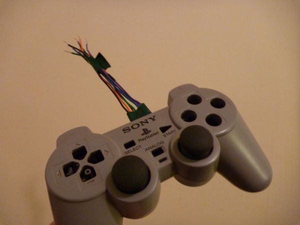
The controller is really easy to take apart. First unscrew the 7 Phillips head screws on the outside of the controller. When you open it up, you’ll see one more screw on the right of a clear plastic piece (the plastic piece just reflects a small LED that’s mounted on the main PCB) which is necessary to screw everything back together (if you’re not planning on using the controller case again, you can just toss it). Unscrew the last screw and cut the white wire ribbon holding the thumbsticks to the main PCB (cut it so that you have a lot of wire ribbon on your end–it makes the soldering much easier).
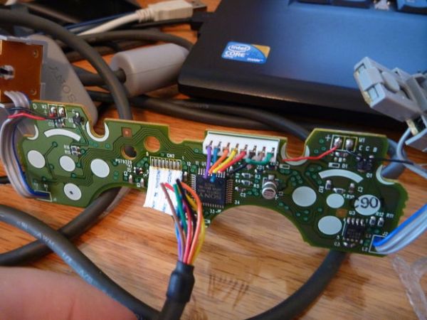
I could have desoldered the joysticks and buttons and used them individually, but I wanted them together as a whole since it’s a good way to have really compact dual joysticks for a future project (most likely a wireless robot).
Some things to note: there are two different sized rumble motors you can salvage as well as the L1 and R1 shoulder buttons which are in their own casing. I took the motors but tossed the shoulder buttons because I don’t plan on ever using them, but someone might find a use.
I haven’t tried finding the specs for the motors yet, but I assume it must be around 5v. If anyone knows, let me know.
For more detail: PS1 Controller Joysticks with Arduino
- Why extract the thumbsticks instead of using the whole controller?
To avoid needing extra libraries or drivers required when using the entire controller. - What tools are necessary to disassemble the controller?
A small Phillips head screwdriver, knife, soldering iron, and wire strippers are required. - How many screws must be removed to open the controller casing?
You must unscrew seven Phillips head screws on the outside plus one more on the right side of the clear plastic piece. - Can I salvage other components besides the joysticks?
Yes, you can also salvage two different sized rumble motors and the L1 and R1 shoulder buttons. - What voltage do the salvaged rumble motors likely require?
The author assumes they must run around 5v, though specific specs were not found. - Which Arduino pins are assigned to the left joystick buttons in the code?
The left click button is assigned to pin 2 and the vertical potentiometer to A2 while the horizontal is A3. - Does the demo code use any external libraries?
No, the provided code uses standard Arduino functions like Serial.print and analogRead without extra libraries. - What is the purpose of cutting the white wire ribbon during disassembly?
Cutting the ribbon with extra length makes the subsequent soldering process much easier.