Summary of Predator Count Down Box
This article details a "Predator" themed countdown timer built for an engineering course. The project features an Arduino Nano controlling a 16x2 LCD and a red 32x8 dot matrix display to show numbers inspired by the movie *Predator*. When activated via a push button, the timer counts down; upon expiration, a buzzer sounds, and a message appears on the screens urging the user to move. The entire system is housed in a plastic project box with custom mounting for the displays and button.
Parts used in the Predator Count Down Box:
- Arduino Nano
- 16x2 LCD
- 32x8 Dot Matrix display
- Push button
- Project box
- NPN transistor (2N4401)
- Buzzer
- 2k2 Resistor
- 10K trim pot (variable resistor)
- Electronics perforated project board
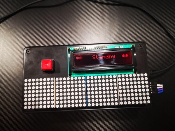
This is a count down timer with some flair!
This project was made as part of an assignment for an online engineering course. The purpose was to have a timer with a set time which would then prompt the user to some action. The timer is activated when the button is pressed, and the LCD screen will simply show the countdown. Once the timer expires there is a buzzer which will sound accompanied by a message on screen to get moving.
Within the parts bin we had a nifty 32×8 dot matrix display… the dots are red. This prompted the idea to also include the countdown numbers using the numbers from the movie the “Predator” movie.
The whole project was put together using an Arduino Nano (any Arduino should work), a 16×2 LCD screen, a 32×8 Dot Matrix module, a button and misc parts. Finally it was all packaged into a plastic project box. Most of these items are easily found on Amazon.
Supplies:
- Arduino Nano
- 16×2 LCD
- 32×8 Dot Matrix display
- push button
- project box
- NPN transistor (2N4401)
- Buzzer
- 2k2 Resistor
- 10K trim pot (variable resistor)
- electronics perforated project board
Step1: Assemble the Screens and Button Parts
You will want to figure out how you want to display all this technology.
You can go with a simple project box as in this example. You could also use an old shoe box, or get creative and make your own enclosure.
Decide how you want to mount the button and the display screens. The screens used in this project had mounting holes in the PCB. I simply made matching holes in the lid of the project box and then strapped in the screens using zip ties. I also made some slots and holes under the screens for the wiring to go through.
You will also want to make and appropriately sized mounting hole for your push button.
Once you have decided on your layout, you can loosely mount your screens.
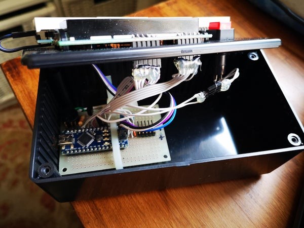
Step 2: Assemble the Arduino and Misc Parts
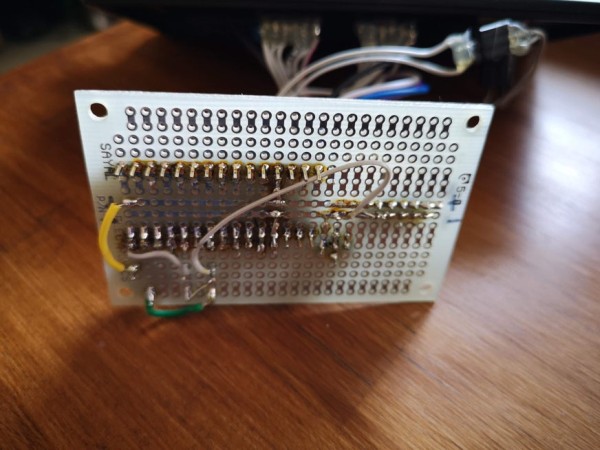
For this step you can either use perf board (a perforated board where you can mount parts and then solder them), or a bread board.
Using the schematic you can start deciding how you want to layout the parts (transistor, trim pot, resistor, buzzer) in order to make the wiring as easy as possible.
Once you have decided on your layout then you can solder the parts into place, ready for the final wiring.
Step 3: Wiring
Using the included schematic, start wiring everything together.
Pay close attention to all the pin outs and pin numbers on every component.
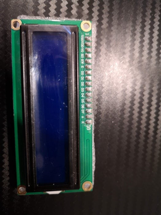
Your 16×2 LCD may or may not have labelled pins so you will need to refer to a data sheet to make sure of your pin out. These are common modules and regardless of who made or sold it, the pin outs will be the same. So you can refer to another vendor’s documentation at times to get the proper pin out.
NOTE – On the schematic, pin 15 and 16 are NC (no connects) but in the attached picture they are labelled A and K for Anode and Kathode. These are for the built in back light LED. You will need to attach A to VCC and K to ground
Once everything is connected you can finish mounting everything into your project box and making sure everything is snug and secure.
Step 5: Load the Code
You will now connect the Arduino to your computer and program it using the Arduino IDE.
If you have never used Arduino, you will find all the information you need at :
https://www.arduino.cc/en/Guide
Now enjoy as your Predator counter does its thing!
Source: Predator Count Down Box
- How is the timer activated?
The timer is activated when the button is pressed. - What happens when the timer expires?
A buzzer sounds accompanied by a message on the screen telling the user to get moving. - Can any Arduino board be used for this project?
Yes, the text states that any Arduino should work, though an Arduino Nano was used. - What kind of display module is used for the countdown numbers?
A 32x8 dot matrix display with red dots is used to show the numbers. - Where can most of these items be found?
Most of these items are easily found on Amazon. - What is the purpose of pin 15 and 16 on the 16x2 LCD?
These pins are for the built-in back light LED, where A connects to VCC and K connects to ground. - What software is required to load the code onto the Arduino?
The Arduino IDE is used to program the board. - How were the screens mounted inside the project box?
The screens were strapped into the lid using zip ties after matching holes were made. - Does the LCD always have labeled pins?
No, the 16x2 LCD may or may not have labeled pins, so a data sheet may be needed.