Summary of Power off from an Arduino Sketch using the Pololu Power Switch
This article demonstrates how to configure an Arduino sketch to power off the system using a Pololu Pushbutton Power Switch. It details wiring a 9V battery and a momentary switch to control power flow, explaining the difference between SV and LV versions. The guide covers connecting the switch's OFF pin to allow software-controlled shutdown and provides instructions for mounting the components on a breadboard or PCB.
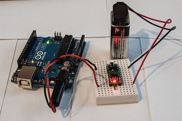
Parts used in the Arduino Auto-Shutdown Project:
- Arduino UNO R3
- Solderless Breadboard
- Pololu Pushbutton Power Switch SV
- 9V battery and holder with power leads
- 2.1mm male power jack
If you need an Arduino to shut off from within your Sketch, this is the solution.
We will explore wiring the Pololu Pushbutton Power Switch, programming the Arduino to shut off the power, and making the unit “power on” only.
The Pololu Pushbutton Power Switch comes in two versions – the SV version geared towards 4.5V-20V range, and the LV which specifies 2.5V-7.0V range. I will use a 9V battery for this demo, and thus the SV version of the power switch.
Webpage for the Pololu Pushbutton Power Switch
Step 1: Getting familiar with the Pololu Power Switch
The power switch has 2 connectors each for GND, VIN and VOUT, allowing multiple attachment points for your projects. A digital connection labeled OFF allows a 5V signal to turn the unit off. The kit comes with 0.1″ headers, making insertion into a Solderless Breadboard effortless, or into a 18-pin DIP for your project.
It also sports 2 connectors for a momentary contact switch, allowing you to use the provided switch directly on the board, or solder your own leads for a switch (or switches) separate from the unit.
Step 2: Setting up the Pololu Power Switch
Attach the 9V battery leads Red to VIN, Black to GND on the Pololu Power Switch
I used a 2.1mm male power jack to plug directly into the Arduino, which regulates the voltage to something the Arduino can handle easily. GND on the Pololu Power Switch goes to the outer connector on the power jack, and VOUT (Red) goes to the inner connector. (See photo)
Pressing the momentary contact switch should power up the Arduino. A second press should turn it off. This is the same behaviour as a standard On/Off switch.
You can choose to either solder the included momentary contact switch to the PCB, or wire it separately to the Breadboard. Wiring it separately means you can use a different momentary contact switch, and/or mount it to your project cabinet. In the early shots of this project, I mounted the momentary contact switch to the PCB for simplicity of the photos, but in the later shots the momentary contact switch is mounted on the Solderless breadboard.
2 – Solderless Breadboard
3 – Pololu Pushbutton Power Switch SV
4 – 9V battery and holder with power leads
5 – 2.1mm male power jack to plug directly into the Arduino
For more detail: Power off from an Arduino Sketch using the Pololu Power Switch
- Which version of the Pololu switch is suitable for a 9V battery?
The SV version is specified for the 4.5V-20V range, making it the correct choice for a 9V battery. - How does the Arduino turn off the power?
A digital connection labeled OFF allows a 5V signal to turn the unit off from within the sketch. - Can I use a different momentary contact switch?
Yes, wiring the switch separately to the breadboard allows you to use a different momentary contact switch. - What are the two voltage ranges available for the Pololu Pushbutton Power Switch?
The switch comes in an SV version for 4.5V-20V and an LV version for 2.5V-7.0V. - How do I connect the 9V battery to the power switch?
Attach the Red lead to VIN and the Black lead to GND on the Pololu Power Switch. - What happens when the momentary contact switch is pressed?
Pressing the switch powers up the Arduino, and a second press turns it off. - How is the VOUT connected to the Arduino?
VOUT (Red) goes to the inner connector of the 2.1mm power jack plugged into the Arduino.