At the place I work, we use xymon to monitor of our servers. All of the services monitored are important, but we wanted a separate indicator to simply show the overall health of the most critical systems. Furthermore, we came up with the following criteria:
- We wanted this visible to everyone whether or not they were near a web browser or even a monitor.
- We wanted it to preserve the “red/yellow/green” status’s xymon uses.
- We wanted it to be stand alone, not requiring a separate computer (we already have one running a widescreen monitor elsewhere for that).
- We wanted it to look good and be fun.
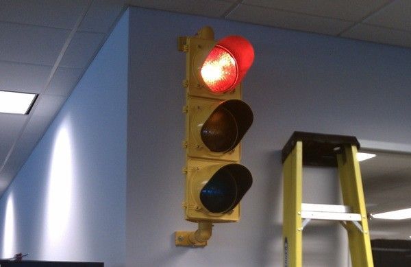
After a little brainstorming, we decided a stoplight equipped with an ethernet enabled arduino would do the trick and I set out to build it.
This article will be of particular interest to you if any of these apply:
- You have a stoplight that you wish could be controlled by a web browser.
- You would you like to learn how to safely control 120volt lamps from an arduino.
- You would you like to learn how to turn an ethernet shield equipped arduino into a simple web server to control outputs.
- You have a “red/green” monitoring system that you would like to have a visible, fun, hard-to-overlook physical component.
I’d sure love to have my own laser cutter. Please see the notes at the end for thoughts on how I would use one, and if you like this article, please rate it and vote for it in the laser challenge.
Step 1: What you need
Below is a list of everything needed to buy if building from scratch. Don’t let the $126 electronics bill scare you; there are a number of ways to save by scrounging and foregoing some cosmetic items. Aside from the Stoplight, the largest costs are the arduino and the Ethernet shield. Obviously if you have either of these items already, this project will cost considerably less (-$30 and -$44.44 ). The two enclosures are not strictly needed, particularly if you are going to stuff everything into a stop light (-$17.46 ). Any 9 volt power supply that can power the arduino can work. There is no need to buy this expensive one if you have one laying around (-$16.68 ). And finally, the ribbon cable (-$3.22 ) can be replaced by any 6 conductor cable or even just 6 wires, and probably doesn’t need to be 4 feet depending on where you put the arduino and the power circuit.
You will need the following tools:
- Soldering iron
- Dremel or other tool to cut and shape the enclosures if needed
- Diagonal cutters
- Hot glue gun (optional)
- Vice or Helping Hands to hold the board while soldering (optional, but recommended)
- Multimeter (for testing the circuit before applying live power)
- Wire wrap tool (optional)
Electronics (Prices in US $ from mouser.com)
| 4- | 1K resistor | — 4 X $0.06 = $0.24 |
| 1- | arduino | — $30.00 |
| 1- | ethernet shield | — $44.44 |
| 1- | arduino enclosure | — $13.33 (optional) |
| 4- | NPN Transistors 2N3904 | — 4 X $0.02 = $0.08 |
| 4- | Diodes 1N4004 | — 4 X $0.06 = $0.24 |
| 6- | break off headers from 32 pin strip | — $0.66 (Optional, and a strip of 36 is 30 more than needed for this project) |
| 1- | 9 pin ribbon cable | — 4 X $0.64 = $2.56 (4 feet, strip off 3 extra conductors and trim to size) |
| 1- | 3 X 2 row break off headers from 10 X 2 strip | — $0.65 (7 more than needed, break of 3 columns) |
| 1- | 9 volt power supply | — $14.30 (any 9 volt power supply should work) |
| 1- | power cord for 9v power supply | — $2.38 (the power supply I ordered didn’t come with a cord!) |
| 1- | screw terminal block with 6 positions | — $1.00 |
| 1- | 2×3 socket for ribbon cable | — $0.66 |
| 1- | protoboard and enclosure (BusBoard KIT-1593L-BK) | — $9.13 |
| 4- | 9 volt relays (fujitsu lz-9HE) | — 4 X $1.85 = $7.40 |
| 4- | 1 Kohm resistors | — 4 $0.04 = $0.24 |
total = $126.83
Other materials:
- Solder
- Wire (at least 22 gauge for the 120v part of the circuit, 18 for stoplight wiring)
- Twist on Wire connectors (for splicing wires inside the light together)
- Power cord (I used one from a PC)
- Working Stop light (http://www.trafficlights.com/polysigs.htm ) — $199 (www.twingreenonline.com has a nice selection of used lights for much cheaper)
- Mounting hardware for light — (http://www.trafficlights.com/polysigs.htm#WMF ) — $99
- 5 amp circuit breaker or fuse — (www.grainger.com ) — $3.38
For testing and hacking the following may be desirable, but are strictly optional:
- Breadboard
- Resistors (180 ohms each will do)
- One each of a Red, Yellow and Green LED
You can order all the mouser items from this project list, or start with that list and subtract anything you don’t need. Mouser apparently didn’t like all the traffic going right to their shopping card and deleted this project without notice. I’ll be updating with actual part numbers later. If you are starting from scratch, make sure you add supplies like solder and wire. As of this writing, mouser does not carry the circuit breaker or stop lights.
Stop lights can found on ebay or on the side of the road after a really good storm*.
* Not really, but you can find them on ebay.
Step 2: Program Arduino and set up ethernet shield
You can extract the arduino sketch from the attached “stoplight.zip” file or Download the latest version from http://code.google.com/p/stopduino/. Open the stoplight.pde file in the arduino IDE and make the following changes before uploading to your arduino:
- Because the stoplight will serve as a server and needs to have a non-changing IP address, the IP address is hard coded in the sketch. You will want to change the line that says “byte ip[] = { 192, 168, 119, 177 }; ” to match the IP address you want to assign the stoplight. Note that the quads that make up the IP address are separated by commas not dots. This is because the IP address is stored as an array of 4 bytes, each of which is one of the bytes of the IP address.
- Do the same thing for the “byte mac[] ” line, substituting the MAC address of your ethernet shield. It should be printed on it somewhere.
- Change the “char secret[] ” array to be whatever password you want to use.
- Change the number in the “EthernetServer server(####) ” line to be whatever port you want the server to listen on. Normally this would port 80.
Program the arduino with your modified sketch, attach the ethernet shield to the arduino, plug it into your network, and then open up a browser window to http://<IP you put in>:<port you put in> or just http://<IP you put in> if you chose port 80 as the port.
Ideally, you should have DNS set up for the stoplight server IP, so you can refer to it as something like http://stoplight.example.com but IP addresses work just as well.

After connecting you should see a simple web page that shows you the current status of each of the lights, complete with check boxes and a place to put your password to change each of them.
If you see the web page appear at all, you will know that your ethernet shield is working, and your arduino is now a web server, even if you can’t see it affecting the outside world yet.
Watching the check boxes change without seeing the arduino do anything is pretty boring, so see the next step for an optional test rig you can build for instant (or at least sooner) gratification.
 stoplight.zip22 KB
1- ethernet shield
4- NPN Transistors 2N3904
4- Diodes 1N4004