Summary of Power Laces- the Auto lacing shoe
This article details a DIY "Power Laces Version 2.0" project inspired by *Back to the Future II*. Using an Arduino Duemilanove and a Motor Shield, the creator built an automatic shoe-tying system. A force sensor detects foot pressure to activate two servo motors that tighten the laces via nylon paracord, while a touch switch loosens them. The build involves modifying a high-top shoe with a custom sheet metal plate and organizing wiring with zip ties and cable loops.
Parts used in the Power Laces Version 2.0:
- A shoe (high-top with padding)
- Arduino Duemilanove
- Motor shield kit from Adafruit.com
- Force sensor
- Servo Motors
- Sheet metal (4" x 4")
- LED and resistors (1K)
- 9 Volt case with battery clip and switch
- Insulated copper wire (high and medium gauge)
- Plastic zip ties (various sizes)
- Plastic 1/2" cable loops
- 1/8" braided nylon paracord (10')
Also, check out Power Laces: Version 2.0
Why wait until 2015?
Inspired by ‘Back to The Future II’, this project is less ‘Practical’ than ‘Proof of Concept’, but hopefully it’ll tide you over until Nike comes out with something more polished.
This was also the first time I worked with an Arduino microcontroller, and I wanted to get some experience with the little guy.
Operation is quite simple- step into the shoe and a force sensor reads the pressure of your foot and activates two servo motors, which apply tension to the laces, tightening the shoe. A touch switch reverses the servos.
Due to budget constraints, I only modified one shoe. Where did I put that darn sports almanac?!
 And if you get a chance, vote for me in the Instructable USB contest!
Step 1: Parts & Tools
Parts:
A shoe // a hightop with a lot of padding and undersole seemed easiest to work with and modify
Arduino // I used the Duemilanove
Motor shield // The kit from adafruit.com works great, and allows control of multiple types of motors
Force sensor // Also got this from adafruit.com
Servo Motors // again, also from adafruit.com. Gotta save on that shipping whenever you can!
Sheet metal // about 4″ x 4″, enough to keep it’s shape but easily trimmed with shears
LED and a couple of resistors // I only had 1K’s laying around, so that’s what I used
9 Volt case, with built in battery clip and switch
Insulated copper wire // I used high and medium gauge
Plastic zip ties, various sizes // I went through a lot of these
Plastic 1/2″ cable loops // used for organizing cables
1/8″ braided nylon paracord // 10′ should be enough
Tools:
Just the basics- soldering iron, screwdrivers, etc. A hot glue gun is handy, too.
Misc:
A USB A to B cable and a computer to load the Sketch to the Arduino.
Step 2: The Laces pt. 1
Cut six lengths of cord, each about 18″ long. Remove the inner core and save for future projects.
Fit the zip ties into the holes for the shoelaces on one side. I fit in 5, leaving one space inbetween each zip tie.
Fit the shell of the cord over the zip tie. Don’t trim the end, as shown in one of the pictures. Keep in long, as later the end of this will connect to the Servo.
I trimmed the “clipping part” off the zip tie, and then used a lighter to melt the cord down, giving it a cleaner appearance. If you apply some quick heat to a 1/4″ area at the end here, it will stiffen and prevent the it from coming out (that’s what she said.)
Repeat for the other four.
Screw on the plastic loops and thread through on the other end.
Save the 6th length of outershell cord for later in the project.
Step 3: The Laces pt. 2
The ankle strap is mounted pretty much the same way as the lower laces. The ankle strap runs the opposite way of the other straps, to put some counter-force on the servos when they put the laces under tension.
I put a small martini shaker into the shoe to act as a foot analog, so I could make strap adjustments and such. You want to be able to get your foot easily into the shoe, and visually the tightening laces look better if they have a lot of slack.
Step 4: Servo Mounting Plate
Leave a bit of a gap between the plate and the shoe for now, as later we’re going to put some zip ties through to attach the servo motors.
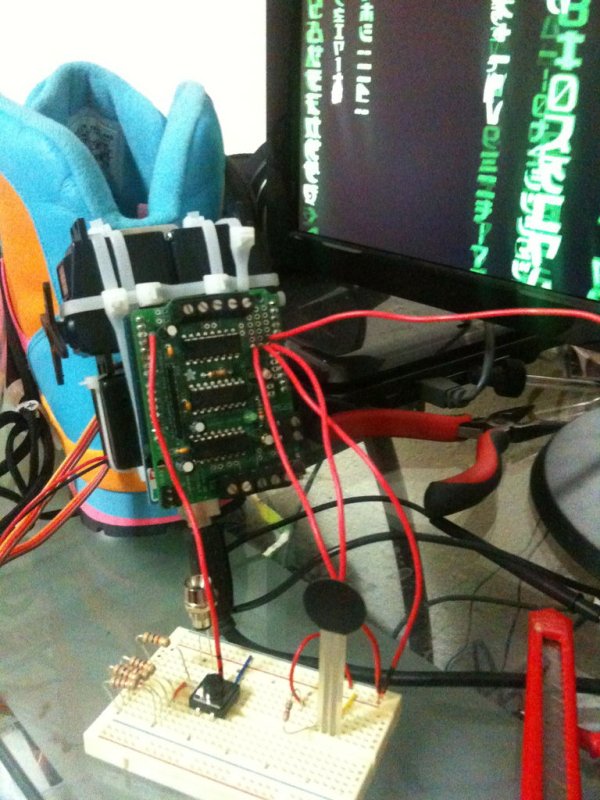
Step 5: Construct the Motor Shield
Following the instructions on the site, solder the Motor Shield together and attach it to the Arduino via the header pins.
For more detail: Power Laces- the Auto lacing shoe
- How does the shoe automatically tighten?
A force sensor reads foot pressure to activate two servo motors that apply tension to the laces. - Can I reverse the tightening process manually?
Yes, a touch switch reverses the servos to loosen the laces. - What microcontroller is used in this project?
The project uses an Arduino Duemilanove for the first time by the author. - How are the laces connected to the motors?
Sheaths of 1/8" braided nylon paracord are threaded through zip ties and connected directly to the Servo motors. - Where is the servo mounting plate attached?
The trimmed sheet metal plate is mounted on the back of the shoe using flat-bottomed screws. - Does the project require multiple shoes?
No, due to budget constraints, only one shoe was modified for this proof of concept. - What tool is recommended for attaching the motor shield?
A soldering iron is needed to assemble the Motor Shield kit before attaching it to the Arduino. - How do you prevent the cord from slipping out of the zip tie?
Apply quick heat to a 1/4 inch area at the end of the cord to stiffen it and lock it in place.